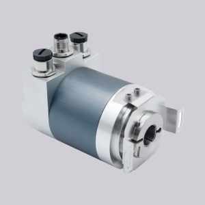
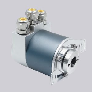
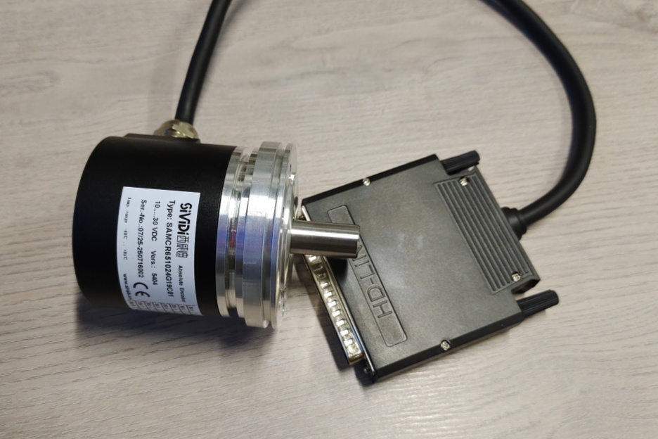
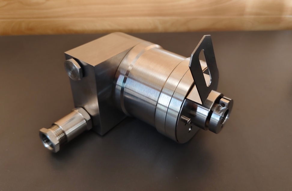
For PSM58N-F2AAZR0BN-1213, EncoderWorks can configure a custom compatible replacement solution around the PROFIBUS address, M12 connector, and scaling boundary rather than treating it as a generic absolute encoder. The failure point is usually not the housing size alone; it is the combination of bus address, termination, binary position format, 12-bit multiturn range, 13-bit singleturn resolution, and recessed hollow-shaft installation. Typical production lead time: 15 working days.
This model is used as a multiturn absolute rotary encoder in systems where position data is transferred through a PROFIBUS network. The replacement must preserve the controller’s expected position range, rotation direction, diagnostic behavior, connector arrangement, and mechanical anti-rotation method so that the machine can restart without bus mismatch, scaling error, or position offset.
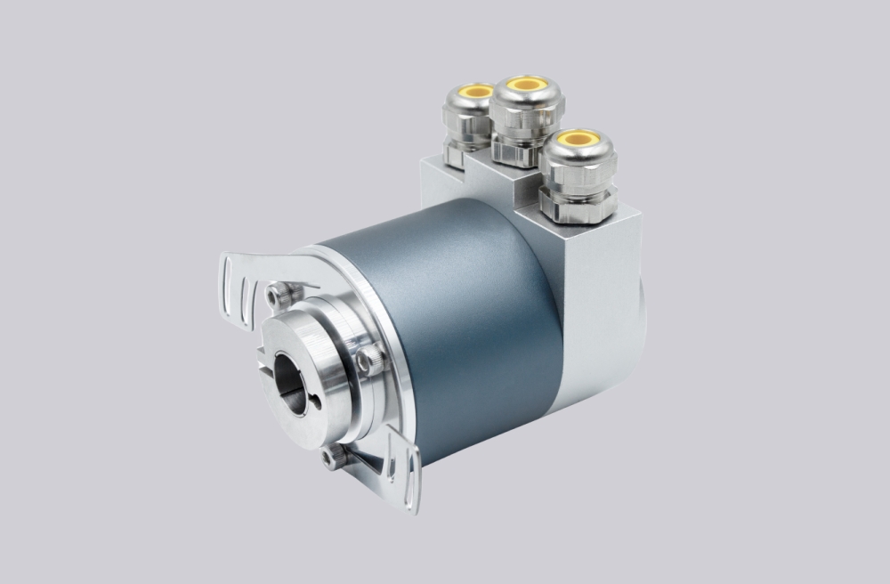
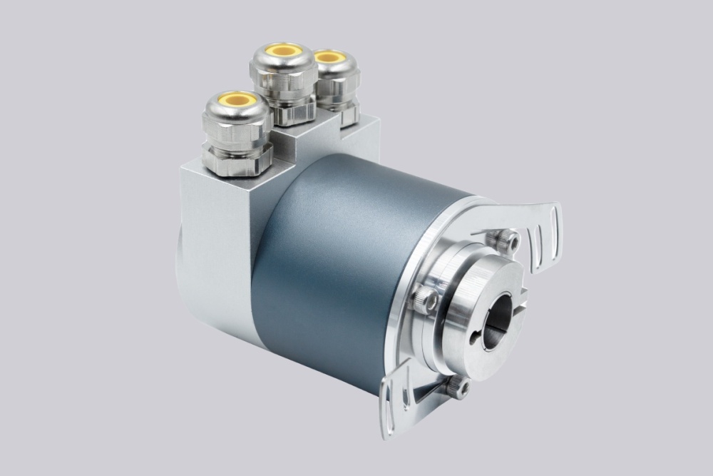
System Limits
The primary system boundary is the PROFIBUS data and scaling relationship. PSM58N-F2AAZR0BN-1213 uses binary position data with a 12-bit multiturn value and a 13-bit singleturn value, so the controller expects a defined total measuring range and a defined number of steps per revolution. If the replacement uses a different resolution, wrong direction setting, incompatible device class, incorrect address, or mismatched parameter length, the PLC may show configuration error, communication loss, wrong position scaling, or a proportional travel error across the full machine stroke. Bus termination is also part of the replacement boundary because an open, duplicated, or incorrectly terminated RS-485 segment can create intermittent data exchange, timeout alarms, or unstable commissioning behavior.
The second boundary is mechanical and installation related. This version uses a recessed hollow shaft with a 12 mm bore and radial M12 connection, so the shaft insertion depth, torque-rest position, cable exit direction, and connector clearance must match the installed machine space. Excessive shaft offset, side load, torque-rest preload, or connector stress can cause bearing load, vibration error, early mechanical failure, or signal dropout during operation. IP exposure also has to be reviewed because water, dust, cable gland stress, or poor connector sealing can turn a correct electrical replacement into an unreliable field installation.
Wiring & Installation
Before replacement, confirm the installed full model code, PROFIBUS address, connector version, controller input configuration, rotation direction, scaling parameters, preset use, diagnostic setting, and whether the machine uses Class 1 or Class 2 functions. The M12 connector arrangement and bus topology must be checked against the existing cabinet and cable route, especially where the encoder is installed between an incoming and outgoing PROFIBUS segment.
During installation, the hollow shaft must sit squarely on the machine shaft without forcing the housing into alignment. The torque rest should prevent body rotation without acting as a rigid lever that loads the bearings. Route bus and power cables away from high-current motor cables, maintain shield continuity, protect the M12 connectors from bending load, and avoid any installation condition that can change the bus impedance, grounding path, or sealing boundary after the machine starts moving.
Custom Compatible Solution
- Match the PROFIBUS interface, binary data format, 12-bit multiturn range, and 13-bit singleturn resolution
- Preserve address setting, bus termination logic, rotation direction, scaling behavior, and preset-related requirements
- Adapt the 12 mm recessed hollow shaft, radial connector exit, housing envelope, and torque-rest mounting boundary
- Review bus wiring, shield continuity, connector stress, IP exposure, shaft offset, and commissioning risk before shipment
Key Data
| Item | Data |
|---|---|
| Model | PSM58N-F2AAZR0BN-1213 |
| Device type | Multiturn absolute rotary encoder |
| Interface | PROFIBUS, RS-485 |
| Data format | Binary |
| Singleturn resolution | 13 bit, 8192 steps |
| Multiturn resolution | 12 bit, 4096 turns |
| Overall resolution | 12-bit multiturn + 13-bit singleturn code combination |
| Supply voltage | 10–30 V DC |
| Connection | AZ, removable housing cover with M12 connectors |
| Cable exit | Radial |
| Shaft / bore | F2A, recessed hollow shaft, Ø12 mm × 30 mm |
| Housing material | N, aluminium, powder coated |
| Option code | 0, no option |
| Expansion code | N, not expanded |
| Protection class | IP65 / IP66 sealing boundary requires confirmation against installed version |
| Key replacement checks | PROFIBUS address, bus termination, scaling, rotation direction, preset use, M12 mapping, hollow-shaft fit, torque-rest preload |