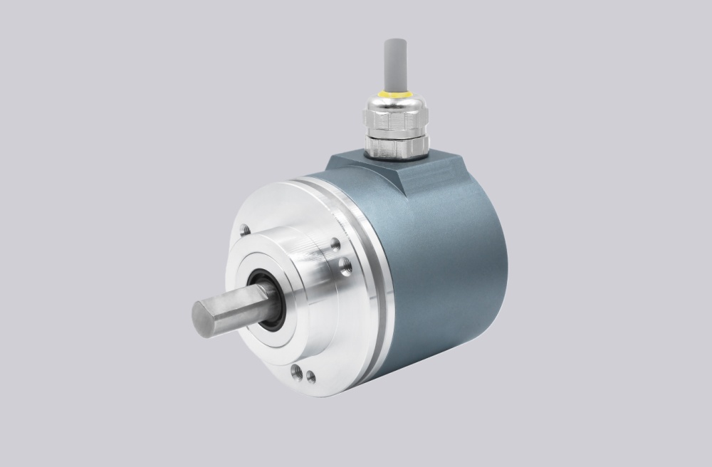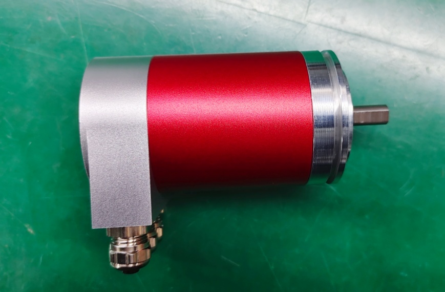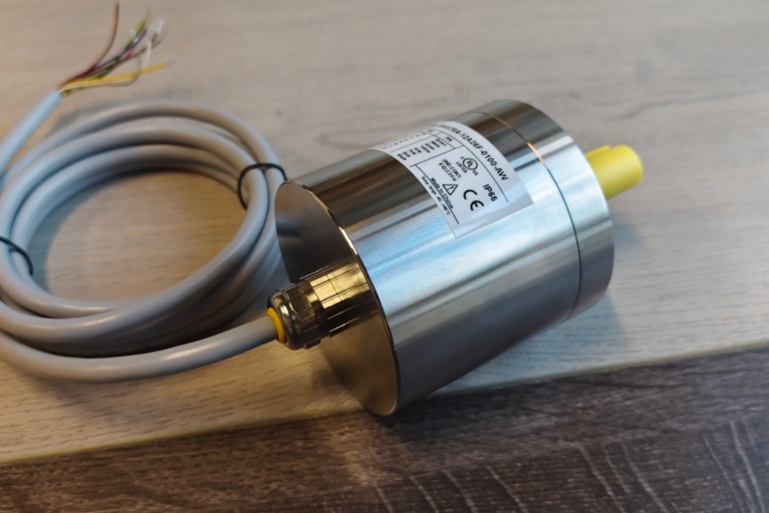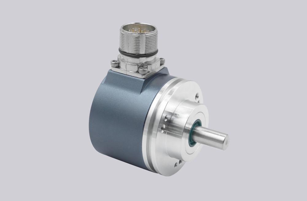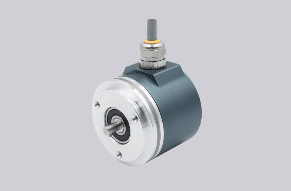



We provide a custom compatible solution for CEV65M-10742, built to reproduce the original parallel absolute feedback behavior through the 39-pin TELDIX axial connector. The key replacement risk is not only matching the encoder body; it is preserving O_D0–O_D23 signal-name mapping, latch capture, preset inputs, and connector-side stability so the controller reads the same position word after installation. Typical production lead time: 15 working days.
Where the System Fails First
The controller reads CEV65M-10742 as a parallel absolute position word. The TELDIX pinout assigns O_D0 to O_D23 across lettered pins from A to a, followed by Direction IN, I_Latch, Preset1_IN, Preset2_IN, RS485 programming lines, ground, and supply voltage. That means the wiring must be checked by signal name, not only by connector shape or pin count.
The failure points are direct:
- Wrong O_D0–O_D23 mapping → corrupted absolute position
- TELDIX letter-pin confusion → bit-order mismatch
- Latch timing error → sampled transition value
- Direction input mismatch → reversed position logic
- Preset1 / Preset2 wiring error → false reference point
- Axial connector strain → intermittent bit-level faults
For CEV65M-10742, the practical replacement boundary is TELDIX letter-pin mapping plus latch capture reliability. A stable replacement must reproduce the original parallel word before mechanical fit can be considered successful.
Connector and Mechanical Boundary
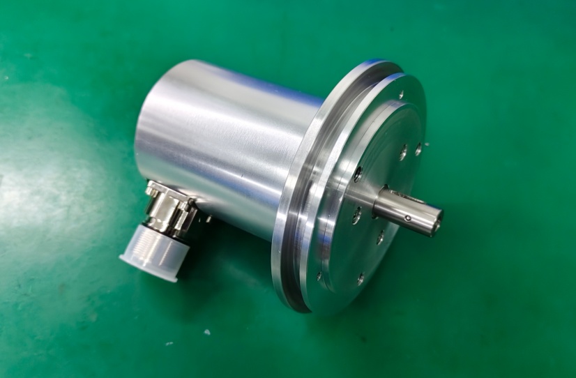
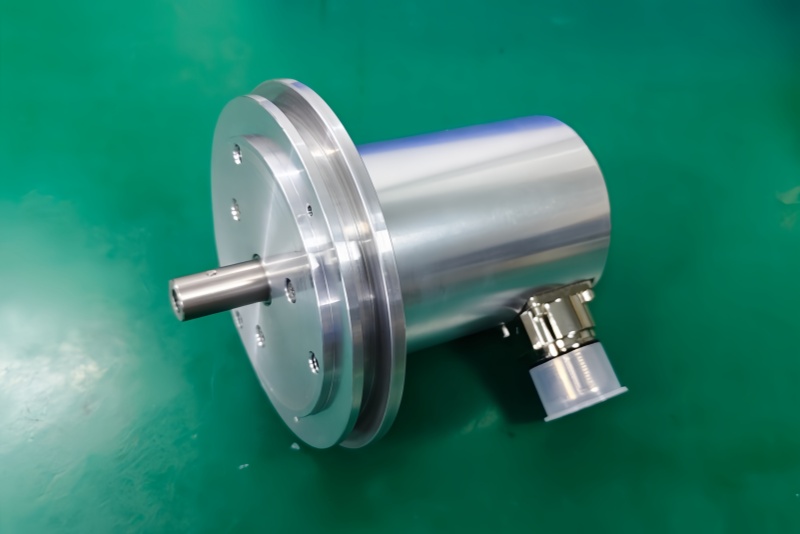
The drawing shows a ZB80 flange, 12FL / 24 shaft, and an axial 39-pin TELDIX connector. Compared with a radial or angled connector layout, the axial connector shifts the field risk toward rear clearance, cable pull, and connector strain. If the machine frame or cabinet route pushes the connector backward, random bit errors can appear before any encoder core fault is visible.
This model uses the larger ZB80 mechanical interface, so flange and shaft fit must be checked carefully. But the more likely commissioning failure is still electrical: one wrong TELDIX lettered pin, one unstable latch input, or one weak shield path can produce a valid-looking but incorrect position value.
Installation Notes
- Keep the model format as CEV65M-10742
- Map O_D0–O_D23 by signal name, not only by TELDIX pin letter
- Confirm I_Latch timing at the controller input
- Verify Direction, Preset1, and Preset2 behavior before startup
- Keep RS485 programming wires separate from parallel data outputs
- Protect the axial TELDIX connector from rear cable pull
- Maintain connector shielding and strain relief
- De-energize the system before wiring or connector work
Key Data
- Model: CEV65M-10742
- Type: Absolute rotary encoder
- Interface: Parallel push-pull
- Code: Programmable
- Resolution: 4096 steps / revolution
- Multiturn range: 4096 revolutions
- Supply voltage: 11–27 VDC
- Output level: 11–27 VDC
- Flange: ZB80
- Shaft: 12FL / 24
- Connector: 39-pin TELDIX
- Connector position: Axial
- Protection: IP65
- Temperature range: -20 °C to +70 °C
- Options: F/R, Latch, Preset 1+2, Programmable
- Pinout: ST138B
- Parameter file: CE833-265
- Firmware: 437865