We provide a custom compatible solution for CEV65M-03323, designed to keep the original parallel absolute feedback readable after replacement. The key risk is the combination of 10 m cable length, O_D0–O_D23 bit mapping, DataBus_disable_IN, and latch timing; if any of these points are wrong, the controller may receive a complete-looking word that is electrically active but position-wrong. Typical production lead time: 15 working days.
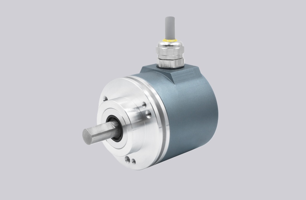
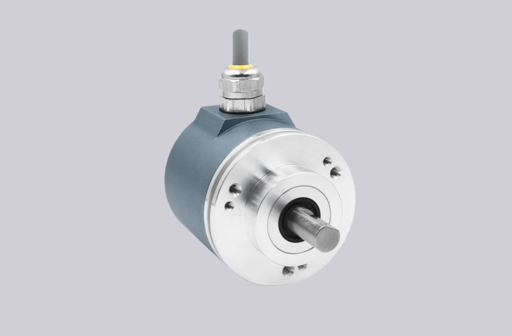
Where the System Fails First
The controller reads CEV65M-03323 as a parallel absolute position word through a 37-pin SUB-D connection. The pinout assigns O_D0 to O_D23 as data outputs, with DataBus_disable_IN on pin 26, Preset1_IN on pin 27, I_Latch on pin 29, Direction IN on pin 30, and Preset2_IN on pin 32. That means replacement accuracy depends on signal-name mapping, not just connector matching.
The failure points are direct:
- Wrong O_D0–O_D23 mapping → corrupted absolute position
- 10 m cable noise → bit-level instability
- DataBus_disable_IN mishandled → outputs enter tristate
- Latch timing error → sampled transition value
- Preset1 / Preset2 wiring error → false reference point
- SUB-D shield weakness → random position jumps
For CEV65M-03323, the practical replacement boundary is parallel word integrity over a 10 m cable plus DataBus-disable control. A stable replacement must keep the output word active, shielded, correctly mapped, and captured at the right latch moment.
Cable and Connector Boundary
This model uses a longer 10 m cable, unlike many similar 0.5 m parallel versions. That changes the field risk. Parallel push-pull outputs are more exposed to EMC, ground reference drift, and cabinet-side noise over longer cable runs. The problem is usually not that all signals disappear; one or two bits become unstable and the absolute value jumps.
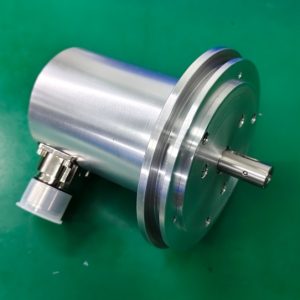
The drawing shows a ZB36 flange, 10FL / 19.5 shaft, PG axial cable exit, and 37-pin SUB-D connector. Mechanically, the layout is familiar. Electrically, the 10 m cable and bus-disable input make this a stricter replacement than a short-cable version.
Installation Notes
- Keep the model format as CEV65M-03323
- Map O_D0–O_D23 by signal name
- Confirm DataBus_disable_IN on pin 26
- Check I_Latch on pin 29 at the PLC input
- Verify Direction, Preset1, and Preset2 behavior
- Keep RS485 programming wires separate from parallel data outputs
- Maintain SUB-D shielding across the full 10 m cable run
- De-energize the system before wiring or connector work
Key Data
- Model: CEV65M-03323
- Type: Absolute rotary encoder
- Interface: Parallel push-pull
- Code: Programmable
- Resolution: 4096 steps / revolution
- Multiturn range: 4096 revolutions
- Supply voltage: 11–27 VDC
- Output level: 11–27 VDC
- Flange: ZB36
- Shaft: 10FL / 19.5
- Connector: SUB-D 37-pin
- Connector position: PG axial
- Cable length: 10 m
- Protection: IP65
- Operating temperature: -20 °C to +70 °C
- Options: BUS, F/R, Latch, Preset 1+2, Programmable
- Pinout: ST2227A
- Parameter file: CE833-265
- Firmware: 437865