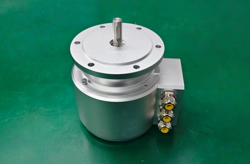
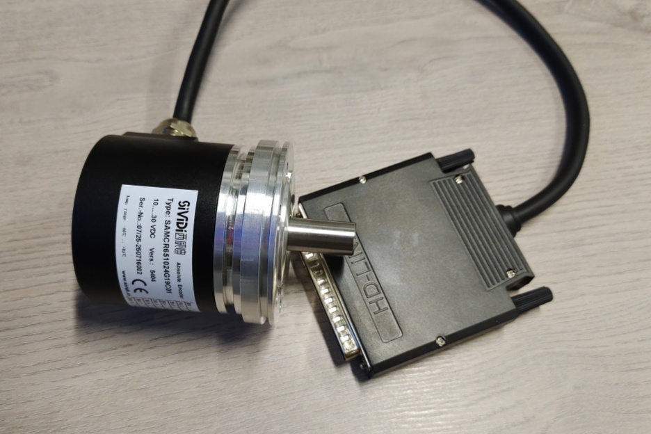
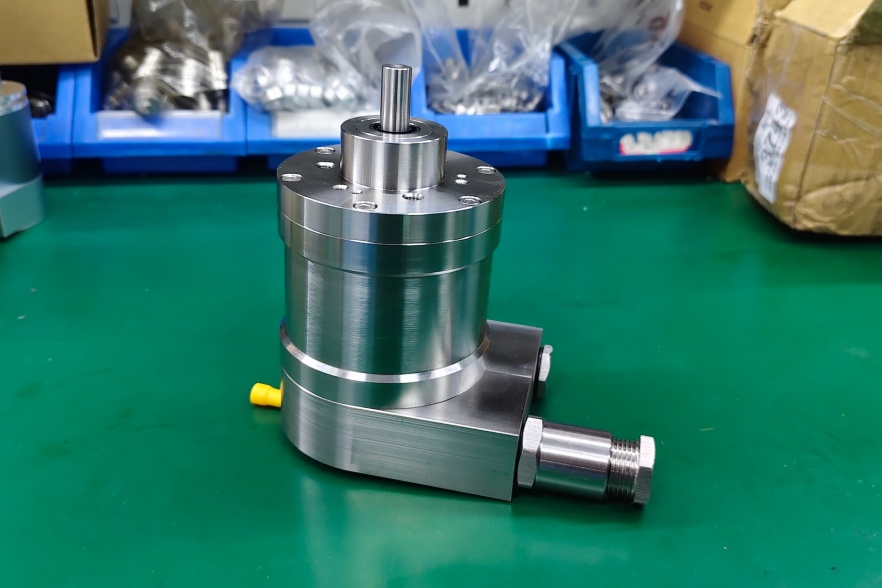
We developed a custom solution for 8.H120.4K6K.2048, for heavy motor and generator systems where 2048 PPR push-pull feedback must stay stable despite shaft current, torsional movement, vibration, and terminal-box wiring risk.
This model should be read directly:
- 4 = 150 mm torque arm
- K = 17 mm conical blind hollow shaft, 1:10
- 6 = push-pull with inverted signals, 10–30 VDC, power type
- K = rotatable terminal box
- 2048 = 2048 pulses per revolution
Typical production lead time: 15 working days.
The weak point is not the optical sensor first. On this structure, the first failures usually appear at shaft fit, torque-arm restraint, clamp force, shielding continuity, or counter frequency margin.
At 2048 PPR, the pulse rate can rise quickly under high motor speed. The encoder output supports up to 300 kHz, but the PLC or drive counter still has to preserve clean A/B/0 edges. If grounding or cable routing is poor, the counter starts losing trust in the signal before the encoder itself fails.
Where the System Fails First
The 17 mm conical hollow shaft is the key mechanical point. If the taper fit or central fastening is not controlled, the encoder can show edge jitter even when the electronics are normal. A bad shaft fit creates micro-movement first, then phase instability, then bearing stress.
For the power push-pull output, cable length and load current are stronger than standard push-pull, but not unlimited. The datasheet gives 350 m maximum cable length at 100 kHz for the power push-pull version. Once the shield path breaks at the terminal box, the signal may still switch, but edge timing is no longer reliable.
Typical failure points:
- Poor taper fit → shaft micro-slip
- Wrong torque-arm restraint → housing oscillation
- Shield discontinuity → unstable A/B edges
- Counter margin too low → missed pulses
- Grounding error → reference pulse instability
- High shaft current without insulation control → feedback damage risk
Mechanical Boundary
H120 is built for heavy machines, but it still depends on installation discipline. The platform provides 2.5 kV bearing isolation, HD-Safety-Lock™, dual shaft protection, IP67, seawater-resistant housing, 475 N radial load, 375 N axial load, and -40 °C to +100 °C operating range. These margins are strong, but they do not correct a loose taper, wrong torque arm, or poor shield grounding.
Installation Notes
- Keep the model format as 8.H120.4K6K.2048
- Treat the 17 mm 1:10 taper as the main mechanical control point
- Use correct central fastening torque for the conical shaft
- Keep the terminal-box shield path continuous
- Separate encoder wiring from inverter and motor power cables
- Confirm counter capacity at real RPM and 2048 PPR
- Check shaft-current isolation before blaming the signal output
Key Data
- Model: 8.H120.4K6K.2048
- Type: Heavy-duty hollow shaft incremental encoder
- Resolution: 2048 PPR
- Output: Power push-pull with inverted signals
- Supply voltage: 10–30 VDC
- Max frequency: 300 kHz
- Max cable length: 350 m at 100 kHz
- Shaft: 17 mm conical blind hollow shaft, 1:10
- Mounting: 150 mm torque arm
- Connection: Rotatable terminal box
- Protection: IP67
- Temperature: -40 °C to +100 °C
- Shaft load: 475 N radial / 375 N axial
- Shock: 2000 m/s², 6 ms
- Vibration: 150 m/s², 10–2000 Hz