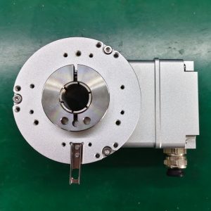
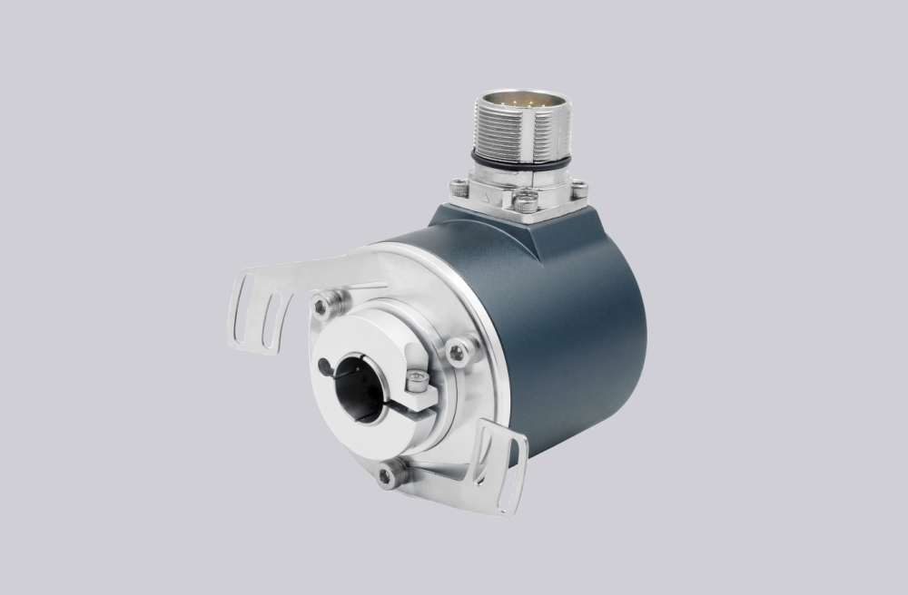
We developed a custom solution for 8.H120.1B5K.1024, for heavy motor and generator systems where 1024 PPR push-pull incremental feedback must remain stable under shaft current, hollow-shaft fit, terminal-box wiring, and industrial EMC conditions.
Model reading:
- 1 = no mounting accessory
- B = 16 mm blind hollow shaft with central fastening
- 5 = push-pull with inverted signals, 10–30 VDC
- K = rotatable terminal box
- 1024 = 1024 pulses per revolution
Typical production lead time: 15 working days.
The weak point is not the optical sensor first. On this configuration, the first failure usually appears at shaft clamping, terminal-box shielding, grounding continuity, or counter-side edge recognition.
At 1024 PPR, counter overload is normally less aggressive than 2048 or 5000 PPR versions, but the system still depends on clean A/B/0 signal edges. The H120 platform supports up to 300 kHz pulse frequency, but poor shielding or grounding can make the PLC lose edge stability long before that limit is reached.
Where the System Fails First
The 16 mm blind hollow shaft with central fastening is the main mechanical control point. If the shaft fit is loose or the fastening force is uneven, the encoder may not fail mechanically at first. It usually shows phase jitter, unstable speed value, or intermittent reference signal behavior first.
For standard push-pull output, the datasheet gives 150 m maximum cable length at 80 kHz. That is enough for many cabinet layouts, but not a license for poor routing. Once the cable runs beside inverter output lines or the shield is broken at the terminal box, the counter may still detect voltage transitions, but the timing is no longer trustworthy.
Typical failure points:
- Loose blind-shaft fit → phase jitter
- Poor central fastening → shaft micro-movement
- Shield break at terminal box → unstable A/B edges
- Grounding error → reference pulse noise
- Weak counter filtering → false counts
- Shaft current without isolation control → feedback damage risk
Mechanical Boundary
H120 is built for heavy machines, with 2.5 kV bearing isolation, HD-Safety-Lock™, dual shaft protection, IP67, seawater-resistant housing, 475 N radial load, 375 N axial load, and -40 °C to +100 °C operating range. These margins help, but they cannot correct a poor hollow-shaft fit or broken shield path.
Installation Notes
- Keep the model format as 8.H120.1B5K.1024
- Control the 16 mm blind hollow shaft fit before checking electronics
- Use correct central fastening and avoid uneven clamping
- Keep terminal-box shielding continuous
- Separate encoder cable from inverter and motor power wiring
- Confirm PLC counter settings at real RPM and 1024 PPR
- Check grounding and shaft-current isolation before replacing the encoder
Key Data
- Model: 8.H120.1B5K.1024
- Type: Heavy-duty blind hollow shaft incremental encoder
- Resolution: 1024 PPR
- Output: Push-pull with inverted signals
- Supply voltage: 10–30 VDC
- Max frequency: 300 kHz
- Max cable length: 150 m at 80 kHz
- Shaft: 16 mm blind hollow shaft with central fastening
- Mounting: No mounting accessory
- Connection: Rotatable terminal box
- Protection: IP67
- Temperature: -40 °C to +100 °C
- Shaft load: 475 N radial / 375 N axial
- Shock: 2000 m/s², 6 ms
- Vibration: 150 m/s², 10–2000 Hz