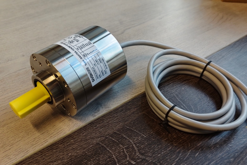
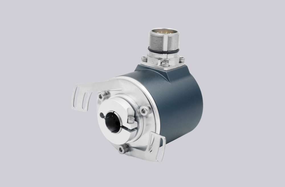
EncoderWorks provides a custom compatible replacement solution for 14-1436X-180 focused on maintaining 10–30 V RS422 differential output behavior, 180 PPR incremental feedback compatibility, and stable controller-side signal reception in heavy-duty industrial environments. The replacement challenge is not only reproducing the pulse output, but also preserving RS422 differential signal characteristics, A/B/0 channel relationships, and receiver-side compatibility. A pulse signal can appear correct during basic testing while incorrect differential matching or phase interpretation still affects machine feedback reliability.
System Limits
The main replacement boundary for 14-1436X-180 is maintaining 10–30 V RS422 differential signal compatibility between the encoder and the controller. This configuration uses 180 PPR incremental output with A/B/0 channels and complementary signals. The replacement must match differential voltage characteristics, receiver input requirements, quadrature phase sequence, and reference pulse behavior because incorrect signal mapping, polarity, or scaling can result in direction errors, unstable counting, or incorrect position feedback.
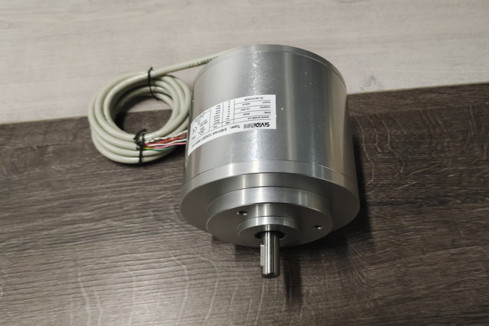
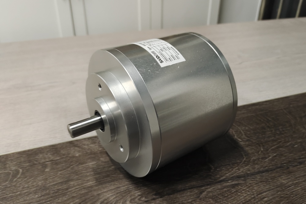
The mechanical integration boundary includes shaft coupling, flange mounting, and industrial environment stability. The 14-1436X-180 uses the heavy-duty series structure with a feather key groove shaft, centering flange design, and reinforced housing for applications with high mechanical demand. Shaft alignment, coupling fixation, vibration resistance, cable routing, shielding, and grounding continuity should be maintained because mechanical stress or electrical interference can affect long-term feedback reliability.
Wiring & Installation
The RS422 interface requires verification of A, A̅, B, B̅, 0, 0̅ differential signal pairs, supply voltage, and protective earth/shield connection. Differential transmission improves noise immunity in industrial systems, but unsuitable receiver input conditions, incorrect signal pairing, poor shielding, or improper grounding may still cause intermittent counting faults or unstable feedback signals.
During replacement installation, the shaft connection, flange centering, and cable routing should be checked against the existing machine structure. The encoder is designed for demanding industrial applications, so mounting stability, vibration conditions, shaft loading, and electrical installation quality should be evaluated together to maintain reliable incremental feedback performance.
Custom Compatible Solution
- Match 10–30 V RS422 differential output and controller-side receiver requirements.
- Preserve 180 PPR A/B/0 quadrature feedback and reference pulse behavior.
- Adapt heavy-duty shaft, flange, and industrial installation requirements.
- Validate differential signal mapping, voltage compatibility, shielding, and grounding conditions.
Typical production lead time: 15 working days.
Key Data
| Parameter | Specification |
|---|---|
| Model | 14-1436X-180 |
| Encoder Type | Incremental Rotary Encoder |
| Output Interface | 10–30 V RS422 |
| Resolution | 180 PPR |
| Signal Output | A / B / 0 and complementary signals |
| Supply Voltage | 10–30 VDC |
| Connection | 9-core Cable |
| Output Frequency | Max. 100 kHz |
| Shaft / Flange | Heavy-duty keyed shaft with clamping flange |
| Protection | IP66 |
| Main Replacement Focus | RS422 differential matching, 180 PPR feedback compatibility, and mechanical adaptation |