Selecting the right encoder for an industrial application is not simply a matter of matching shaft size or resolution. In practice, encoder selection directly affects system stability, signal reliability, commissioning efficiency, and long-term maintenance performance. Many field issues such as unstable feedback, incorrect positioning, or communication failure are not caused by the encoder itself, but by incorrect selection at the initial stage.
A suitable encoder must match not only mechanical structure, but also signal logic, interface type, installation conditions, and control system requirements. For this reason, encoder selection should be approached as a system-level decision rather than a component-level choice.
The first step is to define the application requirement. Before considering any model, it is necessary to understand whether the system requires position feedback, speed feedback, or both. It should also be determined whether absolute position must be retained after power loss or if homing is acceptable, whether the motion is continuous or limited, and how the system is controlled. These factors determine whether an incremental encoder or an absolute encoder is appropriate. Selecting the wrong type at this stage often leads to unnecessary system complexity or operational limitations later.
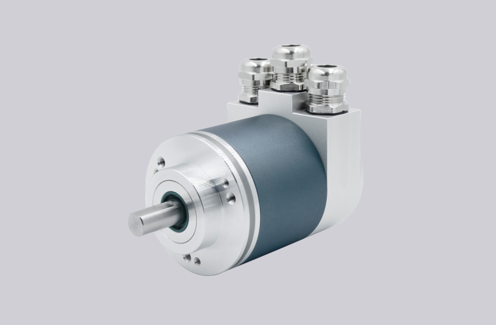
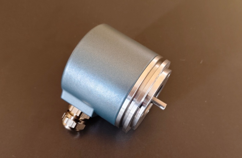
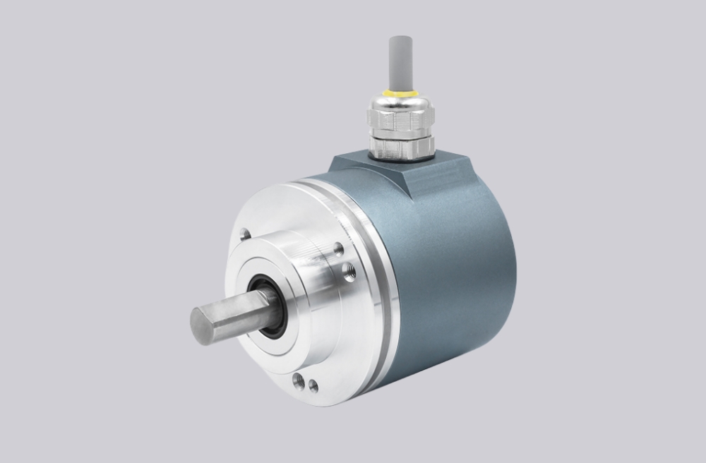
Mechanical compatibility must then be confirmed. Shaft type, shaft diameter, flange structure, mounting interface, installation space, and cable outlet direction must all match the equipment. Even when signal configuration is correct, poor mechanical matching can lead to vibration, misalignment, or premature wear. In many real applications, mechanical mismatch is a common source of long-term instability.
Resolution selection should be based on actual application requirements rather than maximum specification. For incremental encoders, resolution is defined as pulses per revolution, while for absolute encoders it is defined by bit length or position steps. Higher resolution increases signal frequency and system load, and may exceed controller processing capability. In practice, excessive resolution often introduces instability without improving performance.
Matching the output signal or communication interface is one of the most critical steps. Incremental encoders may use TTL, HTL, or open collector signals, while absolute encoders may use SSI, RS485, CANopen, PROFIBUS, PROFINET, or EtherCAT. The encoder must match the controller input exactly. Mechanical compatibility alone is not sufficient. In many cases, an encoder with the correct dimensions fails to function because the signal interface is incompatible with the control system.
Installation environment must also be considered. Temperature range, vibration level, dust, moisture, and electrical noise all influence encoder performance. In high-noise environments, differential signaling, proper shielding, and correct grounding are essential. In harsh conditions, sealing and structural robustness become more important than interface complexity.
Wiring and integration requirements should be evaluated at the same time. Cable length, routing conditions, connector type, and shielding all affect signal stability. Some encoders are simple mechanically but require complex configuration, while others are easy to integrate electrically but require careful signal interpretation. The goal is to reduce overall system complexity rather than selecting a device that is only theoretically compatible.
Power supply compatibility is another practical consideration. Encoders typically operate within defined voltage ranges such as 5V or 10–30V. Voltage drop over long cables, unstable power sources, or incorrect supply selection can lead to unreliable signal output even when all other conditions are correct.
In many industrial projects, replacement and long-term compatibility must also be considered. An encoder should be selected not only for current requirements, but also for ease of replacement, availability of equivalent models, and compatibility with existing control logic. Poor planning at this stage often leads to difficulties during maintenance or system upgrades.
From an engineering perspective, encoder selection is not about choosing the highest specification device, but about identifying the configuration that best matches the control system, installation environment, and application logic. In real-world systems, a well-matched encoder consistently provides more stable performance than a higher-specification device that does not fully fit the application.
This article provides a structured approach to encoder selection and highlights the key factors that determine reliable integration in industrial environments.