Correct encoder wiring is one of the most important parts of stable motion feedback. In industrial systems, many signal problems that appear to be “encoder faults” are actually caused by wiring issues such as wrong channel pairing, poor shielding, unstable power supply, missing grounding strategy, or unsuitable input matching on the controller side.
For incremental encoders, proper wiring does more than make the device run. It affects pulse integrity, direction detection, speed measurement stability, counter accuracy, and long-term reliability in electrically noisy environments. A system may rotate normally at low speed and still fail under higher speed, longer cable distance, or inverter interference if the wiring is not handled correctly.
This guide explains how to wire an incremental encoder step by step, with practical engineering points that matter during installation and commissioning.
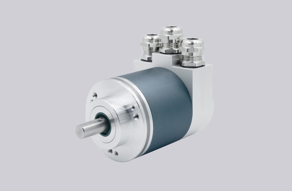
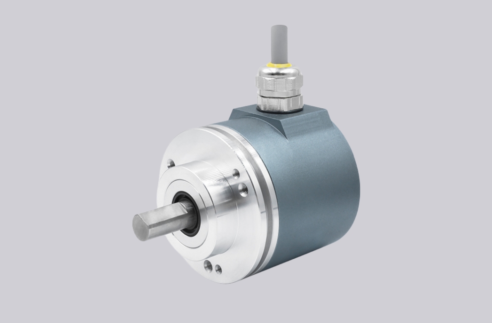
What Signals Does an Incremental Encoder Usually Have?
Most incremental encoders provide the following basic signals:
- Power supply: typically V+ and 0V
- A channel: pulse output
- B channel: pulse output shifted 90 electrical degrees from A
- Z channel: one reference pulse per revolution
- Shield: cable shielding for noise control
Depending on the output type, there may also be complementary signals such as A-, B-, and Z-. These are commonly used in differential signal transmission for better noise immunity.
Before wiring, the first rule is simple:
Do not rely only on wire color. Always confirm the encoder pinout or signal definition first.
Different manufacturers, cable assemblies, and connector types may use different color conventions. Treating color as the only reference is a common cause of miswiring.
Step 1: Confirm the Encoder Output Type
Before connecting anything, verify the output type of the incremental encoder. This is critical because the controller input must match the encoder signal form.
Common output types include:
- TTL / RS422 differential
- HTL / push-pull
- Open collector
- Voltage output variants used in specific systems
This step matters because the same A/B/Z logic can behave very differently electrically. For example, a controller designed for differential TTL input may not read a single-ended HTL signal correctly. Likewise, an open collector output usually needs the correct pull-up arrangement to produce a readable pulse.
From an engineering standpoint, wiring should never begin until these three points are confirmed:
- Encoder supply voltage
- Encoder output type
- Controller input requirement
If any one of these is unclear, the wiring may appear complete but still fail during operation.
Step 2: Confirm the Power Supply
Connect the encoder power supply exactly according to its rated voltage range. Many incremental encoders are built for 5 V, 10–30 V, or another specified supply window. Incorrect supply voltage can cause unstable output, permanent damage, or irregular pulse behavior.
Basic power wiring includes:
- V+ to the correct positive supply
- 0V to system signal reference or controller common according to the control design
During installation, it is good practice to check the actual voltage at the encoder side, not only at the power supply terminal. Voltage drop along long cable runs can create difficult intermittent problems.
A practical field point is this:
An encoder that powers up is not automatically powered correctly.
Undervoltage or noisy supply conditions can still produce weak or unstable signals.
Step 3: Connect A and B Channels Correctly
The A and B channels are the main pulse signals used for movement detection and direction judgment.
Typical logic:
- A and B pulse in quadrature
- The phase relationship determines direction
- Pulse count determines movement amount or speed
For basic single-ended wiring, connect:
- A to controller A input
- B to controller B input
If a Z pulse is used:
- Z to reference or marker input
If the encoder uses differential outputs, wire the complementary pairs correctly:
- A+ / A-
- B+ / B-
- Z+ / Z-
Do not mix single-ended and differential logic casually. Differential systems depend on paired signal transmission. Incorrect pairing may still generate some response during testing, but the signal quality will usually be poor and unreliable under real industrial conditions.
Step 4: Decide Whether the Z Pulse Is Needed
The Z pulse is a once-per-revolution reference signal. Not every application uses it, but when it is required, it must be wired intentionally and interpreted correctly in the controller.
Typical uses of the Z pulse include:
- homing reference
- rotational indexing
- one-turn synchronization
- reference point verification
If the machine logic does not require a reference pulse, the Z channel may remain unused. But if the system depends on homing or angular alignment, omitting Z can cause startup or positioning errors.
A common installation mistake is wiring A and B correctly, leaving Z disconnected, and only later discovering that the PLC or motion controller needs the reference pulse for repeatable homing.
Step 5: Handle Shielding Correctly
Shielding is one of the most overlooked parts of encoder wiring, especially in environments with inverters, motors, relays, brake circuits, and switching power devices.
The shield is not just an extra conductor. It is part of the signal stability strategy.
Best practice in many industrial installations is:
- use shielded encoder cable
- route encoder cable separately from power cable
- avoid long parallel runs with motor output lines
- connect shielding according to the control cabinet grounding strategy
In practice, shielding should be treated as a controlled noise path, not as a random spare wire. Poor shield handling often causes:
- pulse jitter
- unstable counts
- direction errors
- intermittent faults at higher speed
The exact shield termination method may depend on the machine grounding architecture, but one rule is broadly valid:
Encoder cable shielding should be planned, not improvised.
Step 6: Check Grounding and Reference Logic
Signal grounding is just as important as signal connection. Even if A, B, and Z are wired correctly, unstable reference potential can distort pulse reading.
Pay attention to:
- controller signal common
- encoder 0V reference
- cabinet grounding quality
- possible ground potential differences in large systems
In compact machines, grounding is often straightforward. In larger industrial installations, especially those with long cable distances or multiple cabinets, grounding errors can create false counts or communication instability that is difficult to reproduce consistently.
A practical point from field integration is this:
Many encoder signal problems are not caused by the signal wire itself, but by poor reference conditions around it.
Step 7: Verify Input Compatibility on the Controller Side
After wiring is complete, confirm that the receiving device is configured for the actual encoder signal type.
This includes checking:
- input voltage range
- differential or single-ended mode
- high-speed counter capability
- Z pulse usage
- count direction logic
- pulse multiplication or quadrature settings
For example, if the controller is counting A only, the result will differ from A/B quadrature counting. If the direction appears reversed, the issue may be channel assignment or software interpretation rather than a hardware defect.
Wiring and configuration should always be checked together. Stable hardware connection alone does not guarantee correct motion feedback.
Step 8: Test Rotation Direction and Pulse Stability
After installation, rotate the shaft slowly and verify:
- pulses are detected
- direction changes correctly when rotation reverses
- Z pulse appears at the expected rotational point
- no counts are lost at low speed
Then repeat testing at operating speed if possible. Some wiring issues only appear under dynamic conditions, especially when electrical noise increases during machine motion.
A stable commissioning routine should include:
- static power check
- slow manual rotation test
- normal-speed operation test
- repeatability check after stop/start cycles
This process helps distinguish real encoder problems from installation-related faults.
Common Wiring Mistakes
Several mistakes appear repeatedly in industrial encoder installation:
Using wire color as the only reference
Cable color can vary between models and suppliers. Always verify the signal assignment.
Ignoring output type
Mechanical fit does not guarantee electrical compatibility. TTL, HTL, and open collector outputs must be treated differently.
Poor shield routing
Running encoder cable beside motor power cable can create unstable pulse behavior, especially in inverter-driven systems.
Missing signal reference check
Even when pulses are present, incorrect common reference can produce false or drifting counts.
Assuming Z is optional without checking control logic
Some systems need the reference pulse even if the machine seems to move normally without it.
Practical Selection Note
When replacing an existing incremental encoder, correct wiring depends on more than just mounting size. Engineers should verify:
- supply voltage
- output type
- resolution
- cable outlet or connector form
- controller input requirements
- shielding and grounding conditions
A replacement encoder can be mechanically compatible and still behave incorrectly if the wiring logic is not matched to the existing control system.
Final Thought
Wiring an incremental encoder is not only about connecting A, B, and power. It is about making sure the signal remains readable, stable, and compatible with the control architecture under real industrial conditions.
A correct wiring job reduces commissioning time, improves feedback stability, and prevents many of the intermittent faults that are often misdiagnosed as encoder failure. In engineering practice, signal integrity, reference control, and installation discipline are just as important as the encoder itself.