We provide a custom compatible solution for the CEV65M-01542 encoder, focused on systems where 8192 × 4096 absolute feedback must stay stable over PROFIBUS-DP through RS485 wiring, fieldbus hood termination, preset input logic, and correct station addressing.
Model reading from the document:
- CEV65M-01542 = absolute rotary encoder
- 8192 steps per revolution
- 4096 revolutions
- PROFIBUS-DP interface
- Programmable code
- RS485 output level
- 11–27 VDC supply
- ZB36 flange
- 10FL / 19.5 shaft
- 3 × PG9 radial cable entries
- IP65 protection
- -20 °C to +70 °C operating temperature
Typical production lead time: 15 working days.
This model should be judged as a fieldbus feedback node, not as a simple encoder. The first weak point is usually Profibus termination, station address, certified bus cable, RS485 shielding, preset wiring, or parameter mismatch. If the bus is not stable, the encoder may be mechanically normal but still invisible or unreliable at the PLC.

Where the System Fails First
The document specifies PROFIBUS-DP V0, PNO Encoder Profile Class 1 and 2, transmission rate 9.6–12000 kbit/s, and 250 µs cycle time. That makes the bus layer the main risk. Resolution is not the first problem; communication integrity is.
Typical failure points:
- Wrong station address → PLC cannot identify the encoder
- Incorrect S3/S4 termination → intermittent Profibus faults
- Poor RS485 shielding → unstable telegrams
- Wrong DataA / DataB wiring → no communication
- Preset input wiring error → wrong reference position
- Wrong scaling or counting direction → valid data, wrong position
The pinout note is critical: if the encoder is the last station in the Profibus line, DIP switches S3 and S4 must be switched on for terminal resistance. Otherwise they must be off. The document also recommends PNO-certified Profibus cable and defines station address setting from 3 to 99 using BCD address switches. These are not optional commissioning details; they decide whether the feedback system works.
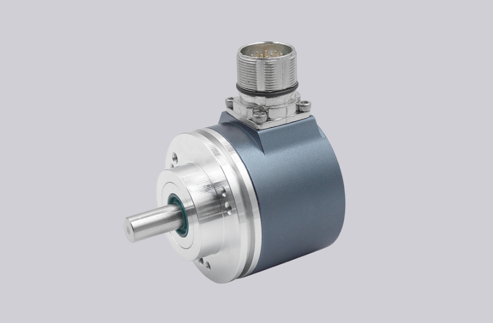
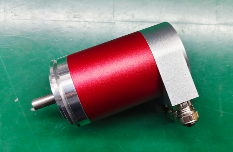
Mechanical and Bus Boundary
The drawing shows a ZB36 flange, 10 mm flat shaft, and a fieldbus hood with 3 × PG7/PG9-style cable entries. The fieldbus hood is part of the system boundary because shielding and incoming/outgoing bus wiring are handled there. A loose shield connection or poor cable gland treatment can produce bus errors before any encoder hardware fault appears.
Mechanically, the platform allows ≤6000 rpm, shaft load ≤40 N axial / ≤60 N radial, and bearing life based on controlled load conditions. If the shaft coupling is rigid or misaligned, the bus will not explain the root cause; the symptom may appear as unstable position feedback or repeated commissioning faults.
Installation Notes
- Keep the model format as CEV65M-01542
- Set the Profibus station address correctly before commissioning
- Use S3/S4 termination only when the encoder is the last bus station
- Wire DataA / DataB / US / GND exactly as defined
- Use certified Profibus cable and keep shielding continuous through the fieldbus hood
- Verify preset input logic before setting the machine reference
- Check scaling, output code, counting direction, and gear function in the PLC
- Keep shaft load within the documented axial/radial limits
Key Data
- Model: CEV65M-01542
- Type: Absolute rotary encoder
- Interface: PROFIBUS-DP
- Profile: PNO Encoder Profile Class 1 / Class 2
- Code: Programmable
- Resolution: 8192 steps / revolution
- Multiturn range: 4096 revolutions
- Output level: RS485
- Supply voltage: 11–27 VDC
- Transmission rate: 9.6–12000 kbit/s
- Cycle time: 250 µs
- Flange: ZB36
- Shaft: 10FL / 19.5
- Connector: 3 × PG9 fieldbus hood
- Protection: IP65
- Operating temperature: -20 °C to +70 °C
- Mechanical speed: ≤6000 rpm
- Shaft load: ≤40 N axial / ≤60 N radial
- Vibration: ≤100 m/s², 50–2000 Hz
- Shock: ≤1000 m/s², 11 ms
- Option: 12 Mbaud
- Pinout: TR-ECE-TI-D-0017