EncoderWorks builds a concise custom compatible solution for CEV65S-10089, focused on preserving the original singleturn parallel push-pull feedback over its 7 m cable and radial 25-pin SUB-D connection. The replacement fails when the controller receives the 8192-step absolute word through a longer cable path but the shielding, latch timing, O_D0–O_D15 mapping, or Gray/programmed decoding is not kept stable. Typical production lead time: 15 working days.
Where the System Fails First
The controller reads CEV65S-10089 as a singleturn parallel absolute position word. The pinout assigns O_D0 to O_D15 as data outputs, with Direction IN on pin 17, Preset1_IN on pin 18, I_Latch on pin 20, RS485 programming lines on pins 22 and 23, supply voltage on pin 24, and ground on pin 25. This makes the replacement boundary different from bus-disable versions: there is no DataBus_disable input here, so the main risk is stable 16-bit word capture over the 7 m cable.

This replacement fails when the encoder body fits but the PLC samples a transition state, receives one noisy bit, or keeps the wrong singleturn scaling after replacement.
The practical fault path is direct: O_D0–O_D15 must be mapped by signal name, I_Latch must capture a stable word, and the 7 m SUB-D cable must keep shield continuity across the cabinet route. A single unstable data line can create a wrong absolute value while the encoder still appears powered and mechanically normal.
A stable replacement must first reproduce the original 8192/1 singleturn word, latch timing, and 7 m cable signal stability before mechanical fit can be accepted.
Cable and Connector Boundary
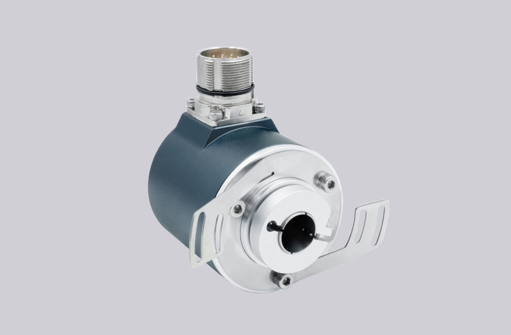
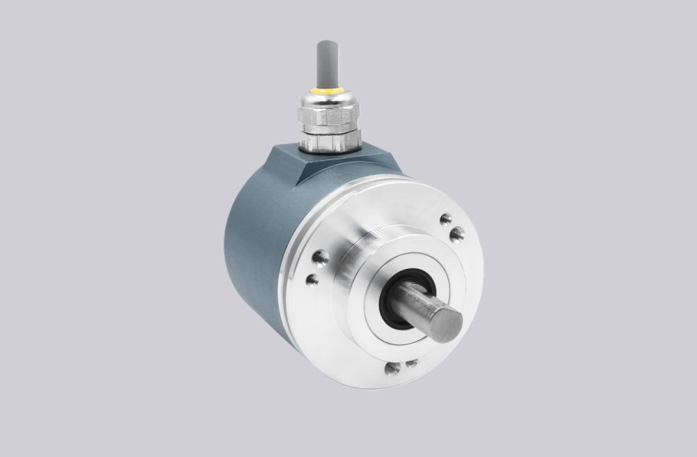
The drawing shows a ZB36 flange, 10FL / 19.5 shaft, PG radial cable outlet, 7 m cable, and a 25-pin SUB-D connector. The 7 m cable is the unique field checkpoint for this model. Compared with short-cable or direct connector versions, it increases exposure to EMC, cabinet grounding problems, and shield discontinuity.
The connector is radial, so cable bend and side pull must be managed at the housing outlet and at the SUB-D end. If the cable is routed near inverter output wiring or motor power lines, the first symptom may be a random position jump rather than a complete signal loss.
Installation Notes
- Keep the model format as CEV65S-10089
- Map O_D0–O_D15 by signal name
- Confirm I_Latch on pin 20 before startup
- Verify Direction on pin 17 and Preset1 on pin 18
- Confirm 8192 / 1 singleturn scaling at the controller
- Maintain shielding across the full 7 m cable
- Keep RS485 programming wires separate from parallel data outputs
- De-energize the system before wiring or connector work
Key Data
- Model: CEV65S-10089
- Type: Absolute rotary encoder
- Interface: Parallel push-pull
- Code: Programmable
- Resolution: 8192 steps / revolution
- Revolutions: 1
- Supply voltage: 11–27 VDC
- Output level: 11–27 VDC
- Flange: ZB36
- Shaft: 10FL / 19.5
- Connector: SUB-D 25-pin
- Connector position: PG radial
- Cable length: 7 m
- Protection: IP65
- Temperature range: 0–60 °C
- Options: F/R, Latch, Preset1, Programmable
- Pinout: ST2722A
- Parameter file: CEV65S-10089
- Drawing: 04-CEV65S-M0084
- Firmware: 4376AD