We provide a custom compatible solution for the CEV582M-10161 encoder, built for systems where 8192 × 4096 SSI absolute feedback must stay stable through M23 connector wiring, 25-bit SSI data format, Gray code decoding, preset logic, and direction control.
Model reading from the document:
- CEV582M-10161 = replacement reference for CEV58M-00161
- 8192 steps per revolution
- 4096 revolutions
- SSI interface
- Gray code
- 10–30 VDC supply
- ZB36 / D65 flange
- D10 L19.5 D-cut solid shaft
- M23 12-pin radial connector
- SSI data bits: 25
- SSI mono time: 20 µs
- IP65 protection
- -20 °C to +75 °C operating temperature
Typical production lead time: 15 working days.
This model should be judged by SSI timing and connector-side signal integrity, not by resolution alone. At this data length, the first weak point is usually clock quality, RS422 pair routing, M23 shield continuity, controller SSI word setting, preset input handling, or direction logic.

Where the System Fails First
The document defines SSI data bits: 25 and SSI mono time: 20 µs. These two values are not small details. If the controller is set to the wrong SSI length or mono time, the encoder may look connected but return shifted, unstable, or unusable position data.
Typical failure points:
- Wrong SSI bit length → position word shifts
- Wrong SSI mono time → unstable read cycle
- Poor M23 shielding → intermittent RS422 data error
- Wrong Direction input → reversed counting
- Wrong Preset1 / Preset2 wiring → false zero reference
- Mixing RS485 programming lines with SSI lines → commissioning fault
The pinout confirms a 12-pin M23 structure: SSI Clock-/Clock+, SSI Data+/Data-, RS485 programming pair, Direction input, Preset1, Preset2, supply voltage, and ground. That means this is not only a clock/data wiring job. Preset and direction inputs can make the encoder output a clean but wrong absolute value.
Mechanical and Signal Boundary
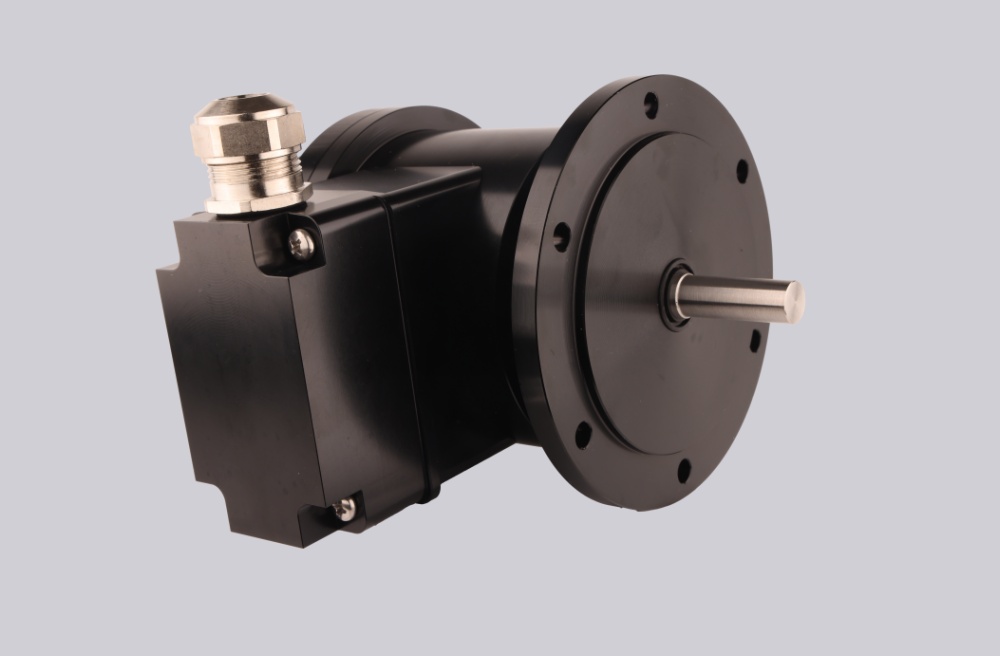
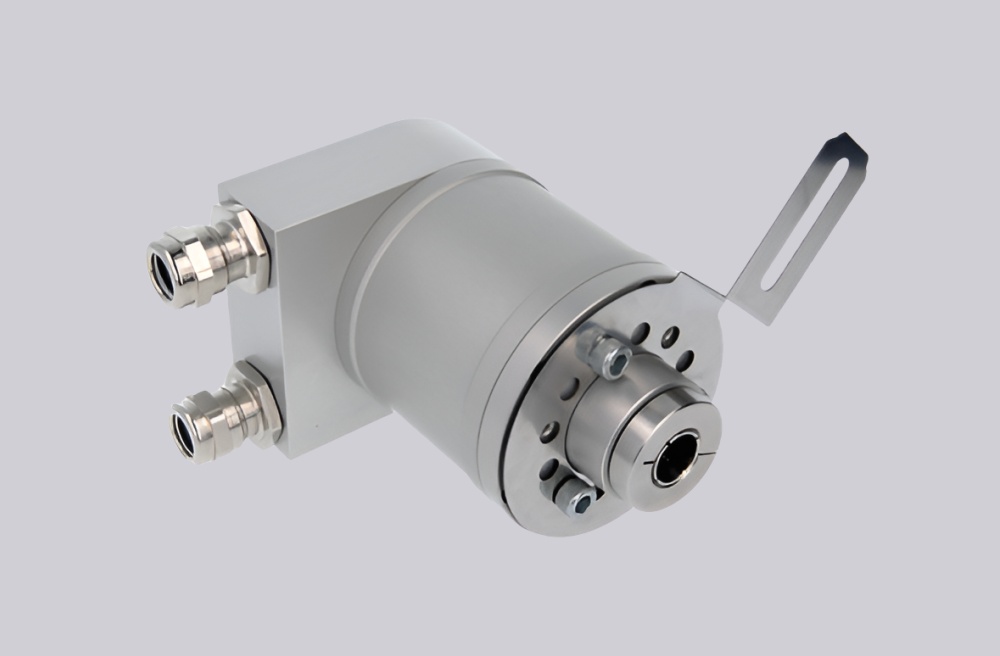
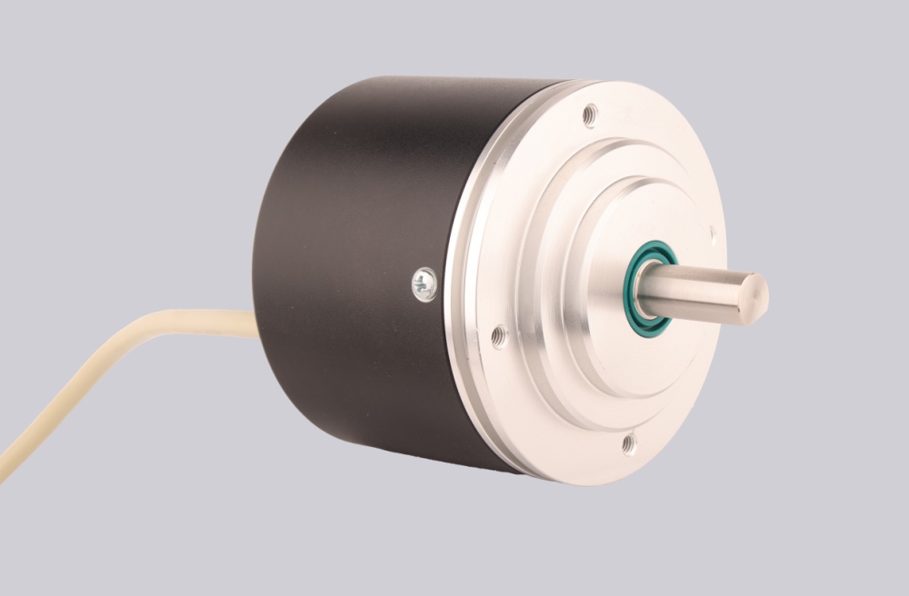
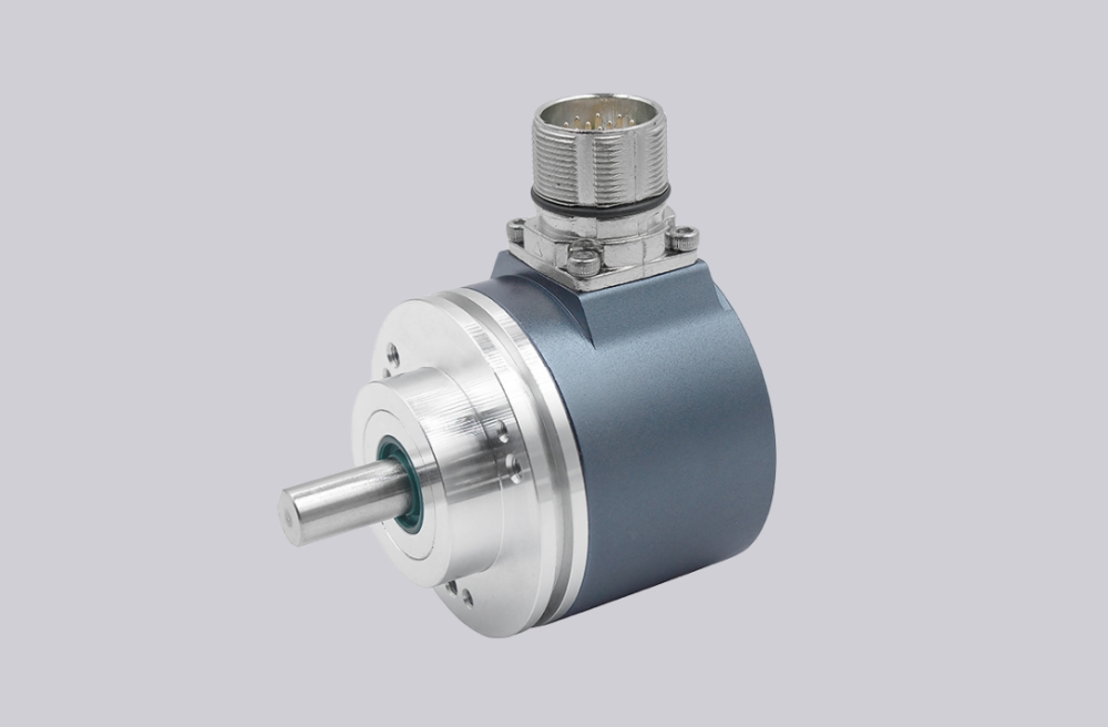
The drawing shows a compact CEV582M body with D10 L19.5 D-cut solid shaft, ZB36/D65 centering flange, and radial M23 12-pin connector. Mechanically, the risk is mainly shaft coupling and connector strain. A rigid or misaligned coupling usually appears first as position instability, not immediate encoder damage.
The document also lists F/R high-active and Preset 1+2. These must be checked during replacement. If the old controller expects the same direction logic and preset behavior, changing wiring without checking these inputs can create a correct signal with the wrong machine reference.
Installation Notes
- Keep the model format as CEV582M-10161
- Match the replacement reference CEV58M-00161 when required
- Configure SSI as 25 data bits
- Keep SSI Clock+ / Clock- as a clean differential pair
- Keep SSI Data+ / Data- as a clean RS422 return pair
- Confirm 20 µs SSI mono time
- Verify Direction, Preset1, and Preset2 before startup
- De-energize the system before M23 connector wiring
Key Data
- Model: CEV582M-10161
- Alternative reference: CEV58M-00161
- Type: Absolute rotary encoder
- Interface: SSI
- Code: Gray
- Resolution: 8192 steps / revolution
- Multiturn range: 4096 revolutions
- SSI data length: 25 bits
- SSI mono time: 20 µs
- Supply voltage: 10–30 VDC
- Shaft: D10 L19.5 D-cut solid shaft
- Flange: ZB36 / D65
- Connector: M23 12-pin, radial
- Protection: IP65
- Temperature: -20 °C to +75 °C
- Options: F/R high-active, Preset 1+2
- Pinout: ST185E
- MTTFd: ≥200 years
- UL approvals: USA + Canada