We provide a custom compatible solution for the 171-01052 encoder, designed for systems where 4096 × 4096 absolute position feedback must stay stable over PROFIBUS-DP, with RS485 bus wiring, fieldbus hood shielding, address setting, and termination logic handled correctly.
Model reading from the document:
- 171-01052 = absolute rotary encoder
- ZE65M*4096/4096 V058 PROFIBUS-DP 36ZB10F
- 4096 steps per revolution
- 4096 revolutions
- PROFIBUS-DP interface
- Programmable code
- RS485 output level
- 11–27 VDC supply
- ZB36 flange
- 10FL / 19.5 shaft
- 3 × PG9 radial connection
- IP65 protection
- -20 °C to +80 °C operating temperature
Typical production lead time: 15 working days.
This model should be judged as a Profibus feedback node, not as a simple absolute encoder. The first weak point is usually not resolution. It is DataA/DataB polarity, station address, S3/S4 termination, shield bonding inside the fieldbus hood, or preset input logic.

Where the System Fails First
The document specifies 12 Mbaud and PNO Profile Class 2. At this speed, bus topology becomes more important than encoder mechanics. A wrong termination setting can produce intermittent faults that look like encoder failure but are actually RS485 reflection or missing reference potential.
Typical failure points:
- Wrong DataA / DataB wiring → no stable Profibus communication
- S3/S4 termination set wrong → intermittent bus faults
- Address conflict → PLC cannot identify the encoder
- Poor shield contact in the hood → unstable telegrams
- Preset input wiring error → wrong reference position
- Wrong programmable code or counting direction → valid data, wrong position
The pinout note is clear: if the encoder is the last station in the Profibus line, S3 and S4 must be switched on for termination. Otherwise they must stay off. The station address is set by BCD switches from 3 to 99, and certified Profibus cable is recommended. These are not setup details; they are the system boundary.
Mechanical and Bus Boundary
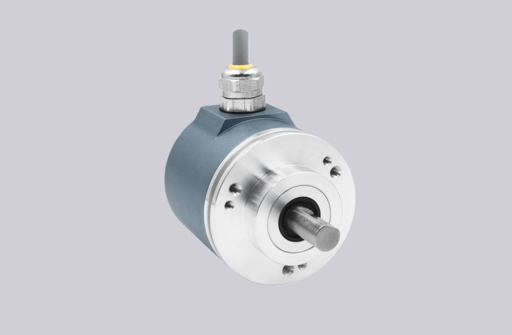
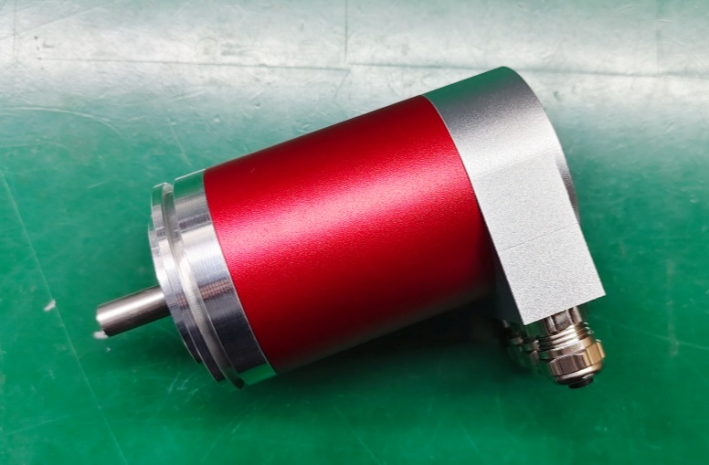
The drawing shows a ZB36 centering flange, 10 mm flat shaft, and a radial fieldbus hood with 3 cable entries. The fieldbus hood is where incoming bus, outgoing bus, supply, grounding, and shielding meet. Most field problems start there: loose shield connection, poor cable gland treatment, or incorrect termination.
Mechanically, this is a compact shaft encoder. The shaft coupling must stay aligned, but the bus will usually fail before the mechanics if the Profibus topology is wrong.
Installation Notes
- Keep the model format as 171-01052
- Wire DataA / DataB exactly as defined
- Set station address before commissioning
- Use S3/S4 termination only at the last bus station
- Keep shield bonding continuous inside the fieldbus hood
- Use certified Profibus cable where possible
- Verify preset input logic before setting machine zero
- Check bus topology before replacing the encoder
Key Data
- Model: 171-01052
- Type: Absolute rotary encoder
- Interface: PROFIBUS-DP
- Profile: PNO Profile Class 2
- Resolution: 4096 steps / revolution
- Multiturn range: 4096 revolutions
- Code: Programmable
- Output level: RS485
- Supply voltage: 11–27 VDC
- Option: 12 Mbaud
- Flange: ZB36
- Shaft: 10FL / 19.5
- Connector: 3 × PG9
- Connector position: PG radial
- Protection: IP65
- Operating temperature: -20 °C to +80 °C
- Pinout: TR-ECE-TI-GB-0017
- Drawing: 04-K171-V0007
- Firmware: 437826