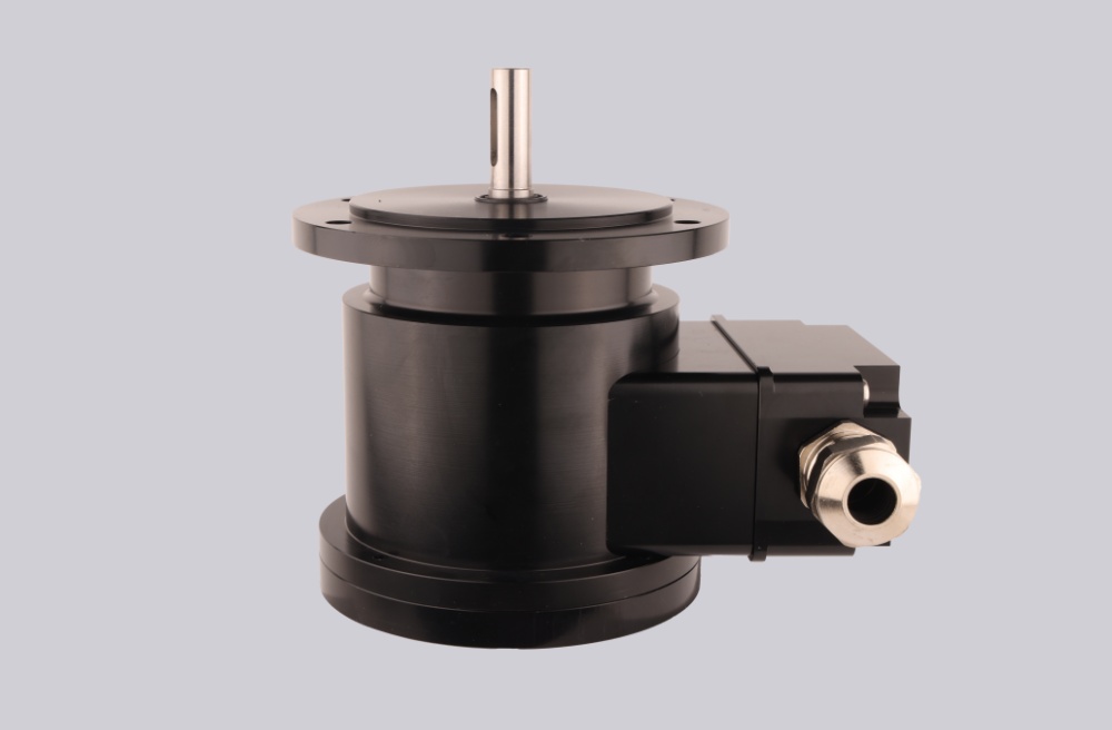
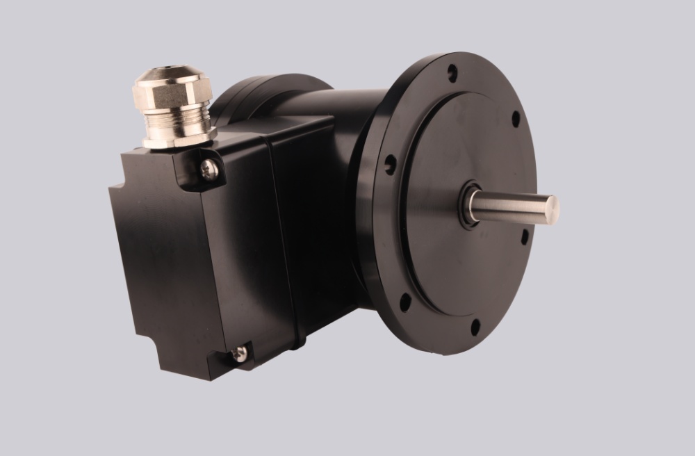
We developed a custom solution for the POG 9G DN 2500 I encoder, intended for heavy-duty drive systems where 2500 PPR HTL incremental feedback must stay stable under high pulse frequency, vibration, terminal-box wiring, and high-temperature operation. This is a single DN feedback configuration, not a confirmed dual-system combination.
Typical production lead time: 15 working days.
Read the model directly:
- DN = K1, K2, K0 output signals
- 2500 = 2500 pulses per revolution
- I = 9–30 VDC, HTL output with inverted signals
- POG 9G = EURO flange B10, Ø11 mm shaft, terminal-box heavy-duty encoder body
At 2500 PPR, the first weak point is no longer the encoder body. The real risk moves to counter bandwidth, HTL edge quality, cable shielding, terminal grounding, and torsional vibration.
Where the System Usually Fails
This model can generate a much denser pulse stream than 500 or 1024 PPR versions. The datasheet gives output frequency ≤120 kHz, so the controller side must be checked against actual RPM before commissioning. High PPR without counter margin leads to missed pulses, unstable speed calculation, or position drift even when the encoder itself is mechanically normal.
Typical failure points:
- Counter frequency limit exceeded → missed pulses
- Poor terminal grounding → false HTL edges
- Shield interruption → unstable high-frequency counting
- Rigid coupling → torsional shock and phase jitter
- Wrong K1/K2 interpretation → reversed direction
- Unstable K0 pulse → reference position error
The K0 zero pulse should not be treated casually at this resolution. In high-vibration drives, reference-pulse instability often appears before continuous K1/K2 signal loss.
Mechanical and Signal Boundary
The POG 9G body is strong: ≤350 N radial load, ≤250 N axial load, ≤12000 rpm mechanical speed, 10 g vibration, 300 g shock, and operating temperature up to +100 °C. But those margins do not solve poor coupling or poor EMC layout. In heavy drives, torsional vibration usually becomes a counting problem before it becomes visible bearing damage.
For this I version, focus on HTL signal stability, not TTL behavior. Keep the encoder cable away from inverter output lines and motor power cables. Once the shield path is broken at the terminal box, the PLC may still detect pulses, but edge timing is no longer trustworthy.
Installation Notes
- Keep the model format as POG 9G DN 2500 I
- Confirm PLC or drive counter capacity at real RPM
- Maintain terminal-box grounding continuity
- Separate encoder wiring from inverter and motor power cables
- Verify K1 / K2 direction before commissioning
- Check K0 stability under vibration
- Use a flexible coupling suitable for Ø11 mm shaft
- Do not treat IP56 as washdown protection
Key Data
- Model: POG 9G DN 2500 I
- Type: Heavy-duty incremental encoder
- Resolution: 2500 PPR
- Output: HTL with inverted signals
- Signals: K1, K2, K0 + inverted
- Supply voltage: 9–30 VDC
- Output frequency: ≤120 kHz
- Shaft: Ø11 mm stainless steel
- Flange: EURO flange B10
- Speed: ≤12000 rpm
- Protection: IP56
- Temperature: -30 °C to +100 °C
- Shaft load: ≤250 N axial / ≤350 N radial
- Vibration: 10 g
- Shock: 300 g
- Connection: Terminal box
- Weight: Approx. 1.7 kg