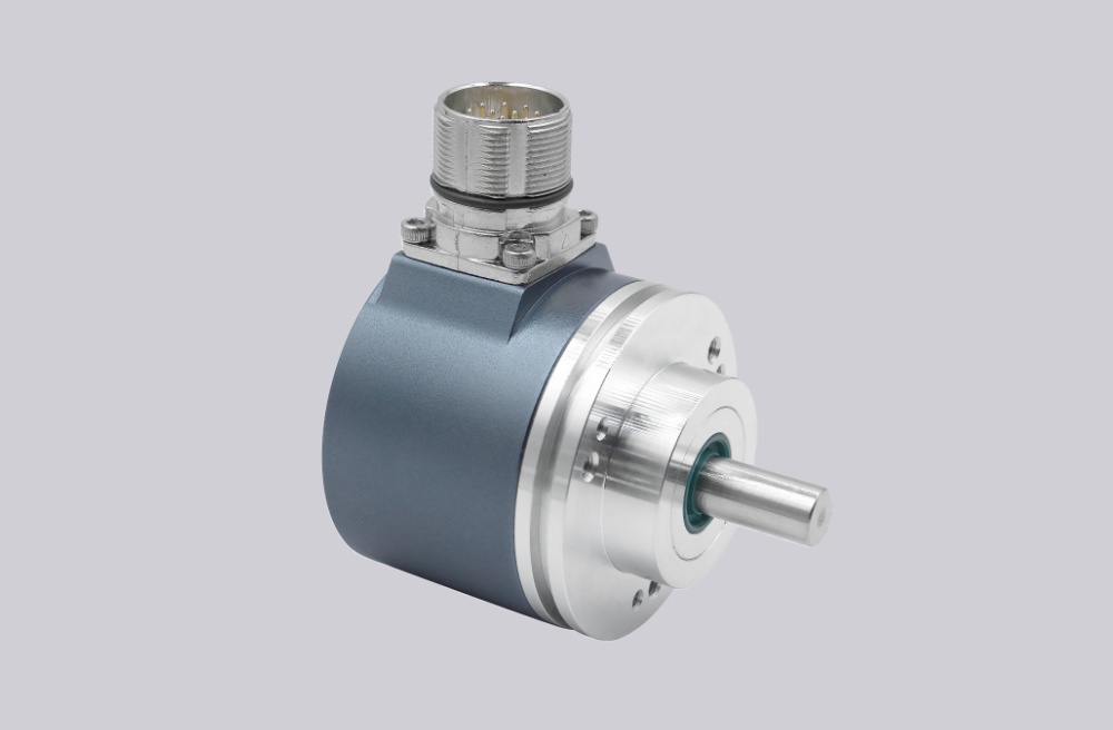
In systems using OCD-PPA1G-0008-SA10-PAP, EncoderWorks can configure a custom compatible replacement solution only when the 8-bit Gray-code mapping, push-pull input level, latch timing, DIR logic, axial M23 pinout, and ø6 mm shaft coupling are preserved together. This is not a serial, fieldbus, or Ethernet encoder; the controller reads the absolute position directly through eight parallel bit inputs. Typical production lead time: 15 working days.
This configuration is used where a compact singleturn absolute encoder must provide direct Bit Parallel position feedback without SSI clock/data, Profibus, Profinet, or EtherNet/IP communication. The encoder combines 8-bit singleturn resolution, Gray code output, push-pull driver behavior, a ø58 mm synchro flange, ø6 mm solid double-flat shaft, and an axial M23 16-pin male connector. Replacement work should focus on Bit 1–8 assignment, input threshold, latch response, DIR input state, connector pin mapping, shaft coupling alignment, and shield continuity.
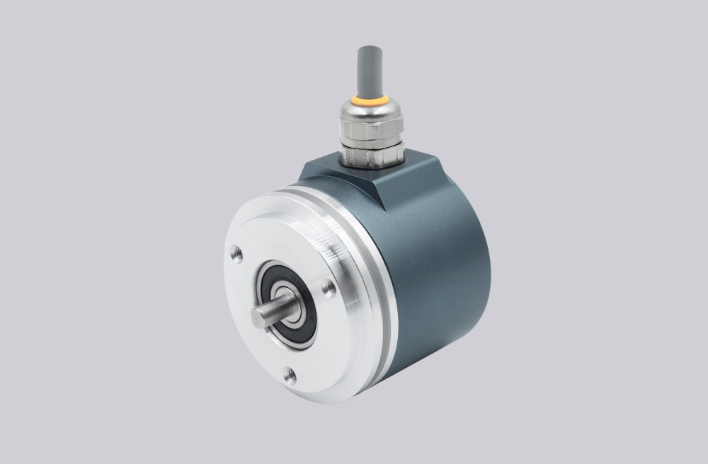
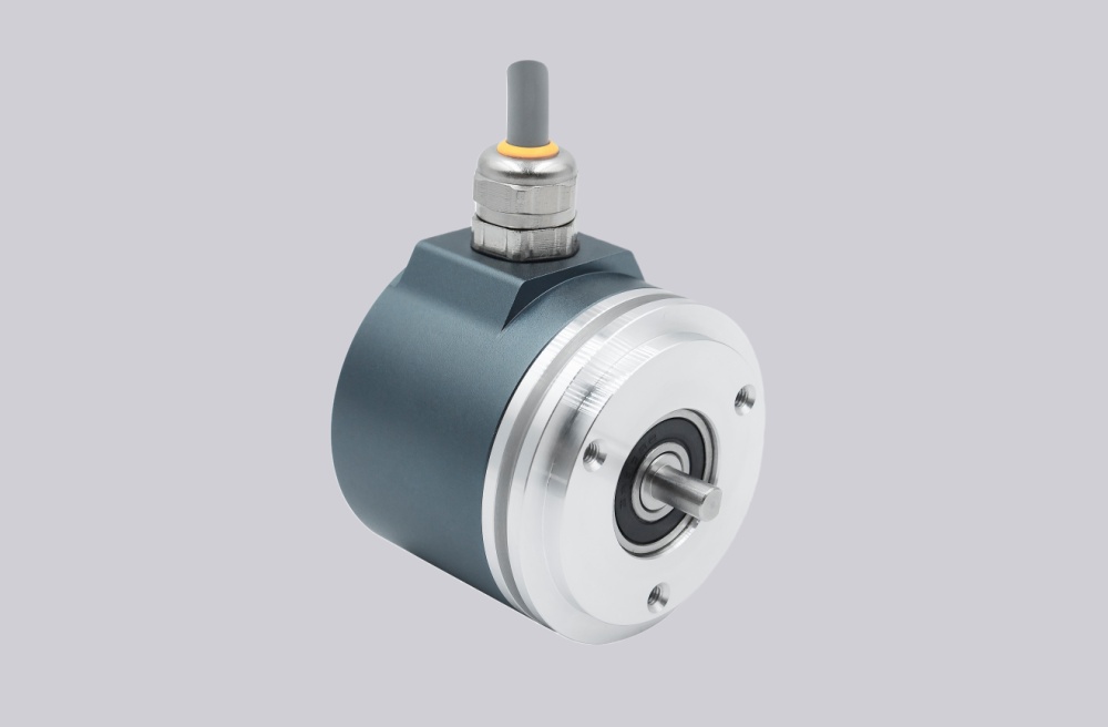
System Limits
The first system limit is 8-bit parallel mapping. Bit 1 through Bit 8 must remain connected to the same controller inputs as the original encoder. If one bit is shifted, inverted, or connected to the wrong input, the controller may receive a stable but incorrect absolute position value.
The second limit is latch and DIR behavior. The latch input must match the controller’s sampling window, while the DIR input must preserve the expected counting direction. If latch timing is unstable or direction logic is reversed, the position value can jump during motion, startup, or reference checks.
The mechanical limit is the ø6 mm solid double-flat shaft and synchro flange. Coupling misalignment, axial preload, radial load, or connector-side cable strain can create bearing stress, repeatability drift, or intermittent feedback faults under vibration.
Wiring & Installation
Before replacement, record the axial M23 16-pin connector wiring for Bit 1–8, DIR, Latch, power supply, GND, and shield. Confirm whether the controller reads Gray code directly or converts it through PLC logic, and check whether the latch input is fixed, pulsed, or synchronized with the control scan.
During installation, align the ø6 mm shaft coupling without axial force and keep the synchro flange square to the mounting surface. Route the parallel signal cable away from inverter and motor power wiring, maintain shield continuity through the M23 connector, and avoid ground loops between the encoder housing, machine frame, and controller earth. After startup, verify zero/reference value, counting direction, bit transition stability, latch response, and repeatability over several machine cycles.
Custom Compatible Solution
EncoderWorks can configure the replacement around the installed controller and mechanical interface:
- Match 8-bit singleturn parallel Gray-code position output and push-pull driver behavior
- Preserve Bit 1–8 mapping, latch input timing, DIR logic, supply range, and controller input compatibility
- Adapt the ø58 mm synchro flange, ø6 mm solid double-flat shaft, coupling, and axial M23 16-pin connector
- Review connector shielding, grounding, EMC routing, controller input threshold, and mechanical preload
Key Data
| Item | Data |
|---|---|
| Model | OCD-PPA1G-0008-SA10-PAP |
| Encoder type | Absolute singleturn encoder |
| Interface | Bit Parallel |
| Resolution | 8-bit singleturn |
| Code | Gray |
| Output driver | Push-Pull |
| Supply voltage | 10–30 VDC |
| Flange | Synchro, ø58 mm |
| Shaft | ø6 mm solid double-flat shaft |
| Connection | Axial M23 male, 16 pin |
| Key signals | Bit 1–8, DIR, Latch, Power Supply, GND |
| Protection | Shaft IP65, housing IP65 |
| Approval | CE |