For the CEV65M-00399 encoder, we provide a custom compatible solution focused on SSI clock integrity, preset reference behavior, RS422 data stability, and 12-pin CONTACT connector matching. The hard part is not only replacing an SSI encoder; it is keeping the same preset values, direction logic, and Gray-code position behavior after installation. Typical production lead time: 15 working days.
This model should be handled as an SSI absolute encoder replacement, not as Profibus, PROFINET, CANopen, analog, or incremental feedback. The controller reads position through the SSI clock/data pair. If the clock pair is noisy or the preset logic is not matched, the encoder may still communicate but return the wrong machine reference.
Where the System Fails First
The pinout defines SSI Clock- / Clock+, SSI Data+ / Data-, RS485 programming lines, Direction input, Preset1, Preset2, supply voltage, and ground. That means the failure boundary is split between two layers: SSI signal integrity and control input behavior.
The real weak points are direct:
- Weak SSI clock pair → unstable position word
- Poor RS422 data shielding → intermittent read errors
- Wrong Direction input → reversed counting logic
- Preset1 / Preset2 mismatch → wrong machine reference
- RS485 programming wires mixed with SSI lines → commissioning fault
- 12-pin CONTACT connector strain → long-term signal instability
The preset values matter here. The document lists Preset1 = 11,000 and Preset2 = 2,097,152. Those values should not be treated as generic inputs. If they are not reproduced correctly, the replacement can output a stable SSI word but still put the machine in the wrong position state.
Connector and Mechanical Boundary
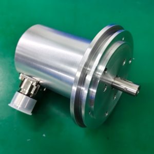
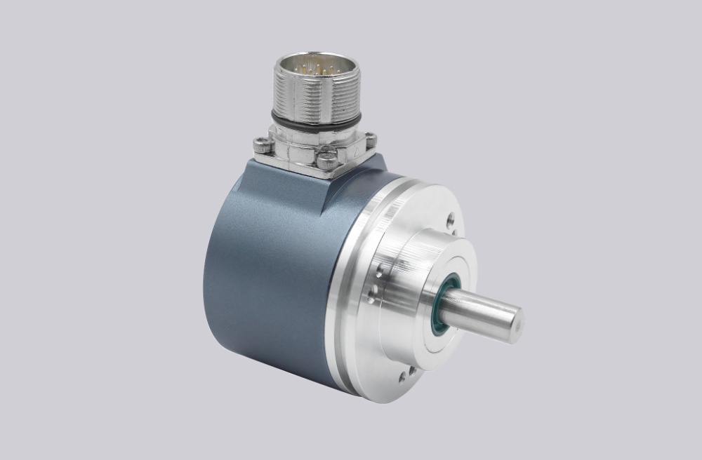
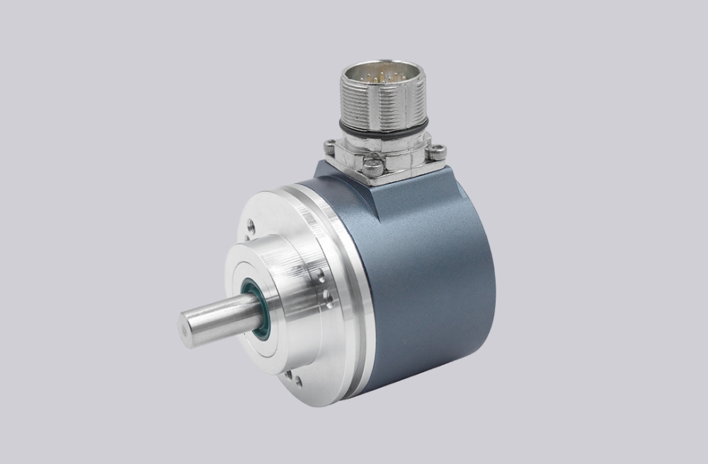
The drawing shows a compact ZB36 flange, 10GL / 19.5 shaft, and a 12-pin Y-coded CONTACT connector mounted laterally on the tube. This connector position is part of the failure boundary. If cable clearance is poor or the connector is side-loaded, SSI errors may appear before any mechanical encoder fault is visible.
The protection level is IP54, so this is not a washdown-style installation. In dusty, wet, coolant, or oil-mist environments, the connector side normally becomes the first reliability concern.
Installation Notes
- Keep the model format as CEV65M-00399
- Keep SSI Clock+ / Clock- as a clean differential pair
- Keep SSI Data+ / Data- as a clean RS422 return pair
- Match Preset1 = 11,000 and Preset2 = 2,097,152
- Confirm Direction input logic before startup
- Do not mix RS485 programming wires with SSI wiring
- Protect the side-mounted 12-pin CONTACT connector from cable strain
- De-energize the system before wiring or connector work
Key Data
- Model: CEV65M-00399
- Previous reference: 110-00399
- Type: Absolute rotary encoder
- Interface: SSI
- Code: Gray
- Resolution: 1024 steps / revolution
- Multiturn range: 4096 revolutions
- Parameterizable: Programmable
- Supply voltage: 11–27 VDC
- Output level: RS422
- Flange: ZB36
- Shaft: 10GL / 19.5
- Connector: 12-pin CONTACT, Y-coded
- Connector position: Side-mounted on housing tube
- Protection: IP54
- Temperature range: 0–60 °C
- Options: Preset 1+2, Programmable, V/R
- Preset1: 11,000
- Preset2: 2,097,152
- Pinout: 185A
- Parameter: 11000399
- Software No.: 909