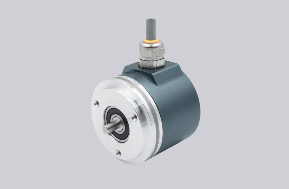
For the CEV65S-10033 encoder, we provide a custom compatible solution focused on parallel bit mapping, latch timing, DataBus tristate control, and SUB-D 25-pin signal stability. This is a singleturn parallel push-pull feedback unit; the real risk is not only reading the position value, but reading all output bits at the correct moment without noise, floating inputs, or connector-side errors. Typical production lead time: 15 working days.
This model is not SSI, Profibus, PROFINET, CANopen, or incremental feedback. It outputs a parallel absolute word through push-pull lines. If the controller samples during a transition, or if one bit line is mapped incorrectly, the encoder may look electrically healthy while the machine position becomes wrong.
Where the System Fails First
The pinout defines O_D0 to O_D15 as data outputs, plus Direction IN, Preset1_IN, I_Latch, DataBus_IN, RS485 programming lines, supply, and ground. That makes the failure boundary very clear: the PLC must read the 16-bit output word cleanly, and it must handle latch and DataBus logic correctly.
The main weak points are:
- Wrong O_D0–O_D15 mapping → corrupted binary position
- Latch timing error → unstable sampled value
- DataBus_IN active at the wrong time → outputs forced to tristate
- Wrong Direction input → reversed counting
- Preset1 wiring error → false reference position
- Weak SUB-D shield or cable strain → random bit errors
The document lists BUS, F/R, Latch, Preset 1, and Programmable options. These are not secondary settings. They decide whether the controller receives a valid singleturn position after startup, preset operation, or replacement.
Connector and Mechanical Boundary
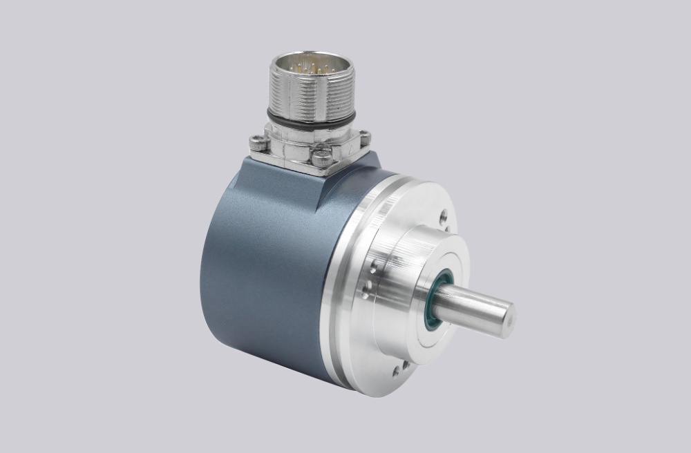
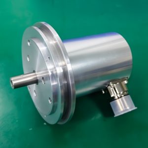
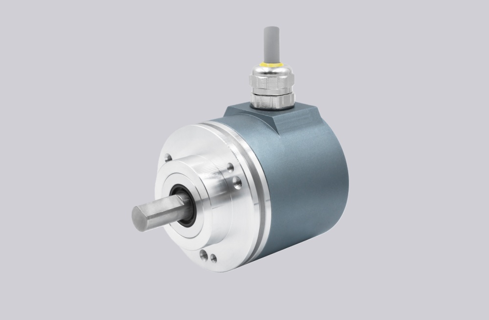
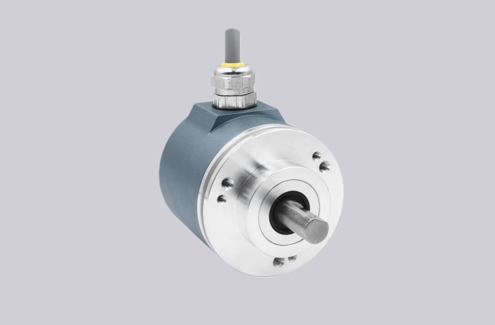
The drawing shows a ZB36 flange, 10FL / 19.5 shaft, radial SUB-D 25-pin connector, and 1.5 m cable. The short cable helps, but the SUB-D connector still becomes the practical failure point when shielding, strain relief, or cabinet routing is poor. Parallel push-pull signals are direct and fast, but they do not tolerate weak grounding or noisy cabinet wiring.
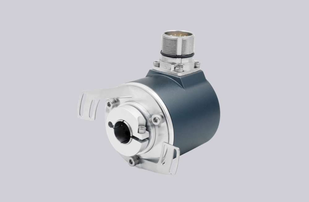
Mechanically, this is a compact shaft encoder. The coupling must stay aligned, but most field faults on this model will appear first as wrong bits, unstable latch capture, or DataBus-related output loss rather than visible shaft damage.
Installation Notes
- Keep the model format as CEV65S-10033
- Map O_D0–O_D15 before checking anything else
- Confirm binary decoding at the controller side
- Check I_Latch timing before replacing the encoder
- Do not activate DataBus_IN unless tristate output is intended
- Verify Direction and Preset1 logic before startup
- Keep SUB-D shielding and cable strain relief solid
- De-energize the system before wiring or connector work
Key Data
- Model: CEV65S-10033
- Type: Absolute rotary encoder
- Interface: Parallel push-pull
- Code: Binary
- Resolution: 8192 steps / revolution
- Revolutions: 1
- Supply voltage: 11–27 VDC
- Output level: 11–27 VDC
- Flange: ZB36
- Shaft: 10FL / 19.5
- Connector: SUB-D 25-pin
- Connector position: PG radial
- Cable length: 1.5 m
- Protection: IP65
- Temperature range: 0–60 °C
- Options: BUS, F/R, Latch, Preset 1, Programmable
- Pinout: 2703A
- WinProg file: CEV65S-10033
- Software No.: 4376AD