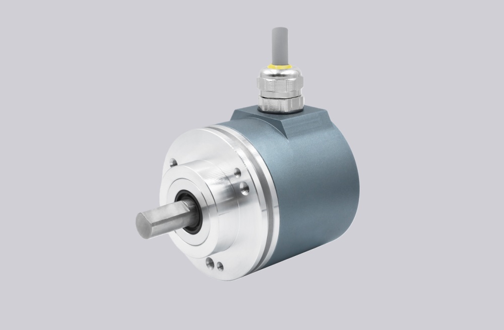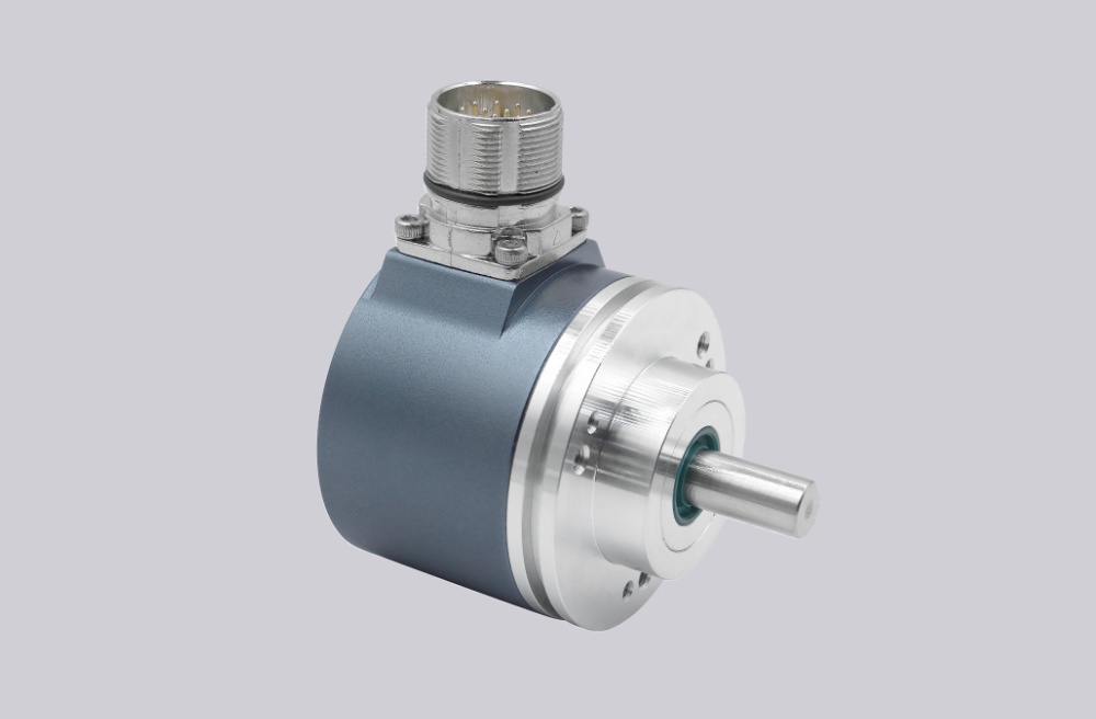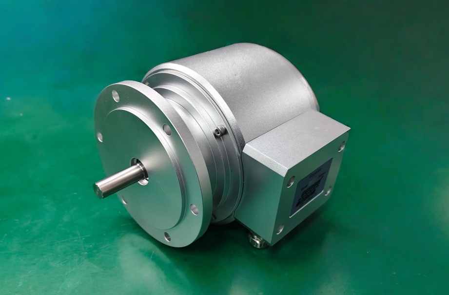



For the CEV65M-10964 encoder, we provide a custom compatible solution focused on parallel word stability, latch timing, SUB-D split wiring, and clean controller-side bit capture. This model is not mainly limited by resolution. The real risk is whether the controller can read O_D0–O_D19 without bit shift, floating inputs, latch timing error, or supply/reference mismatch. Typical production lead time: 15 working days.
This is a parallel push-pull absolute encoder, not SSI, Profibus, PROFINET, CANopen, or incremental feedback. The position value is not transferred as a serial word. It is presented as multiple parallel output lines. If one line is mapped incorrectly, the machine may receive a valid-looking value that is still wrong.
Where the System Fails First
The pinout separates the system into two connector groups. The 25-pin SUB-D carries the parallel outputs, latch, preset, supply, and ground. The 15-pin SUB-D carries the RS485 programming interface plus supply and ground. This split connector structure is the main integration risk. If the wiring is treated like a normal single-connector encoder, commissioning errors become very easy.
The real weak points are direct:
- Wrong O_D0–O_D19 mapping → corrupted absolute position
- Latch timing error → unstable sampled value
- Preset1 wiring error → false reference position
- Programming connector mixed with output wiring → commissioning fault
- SUB-D shield weakness → random bit-level noise
- Supply or ground mismatch between connectors → unstable logic level
The document lists Latch, Preset 1, and Programmable options. These are not minor functions. For this model, latch timing decides whether the controller captures a stable position word or catches the outputs during transition.
Connector and Mechanical Boundary
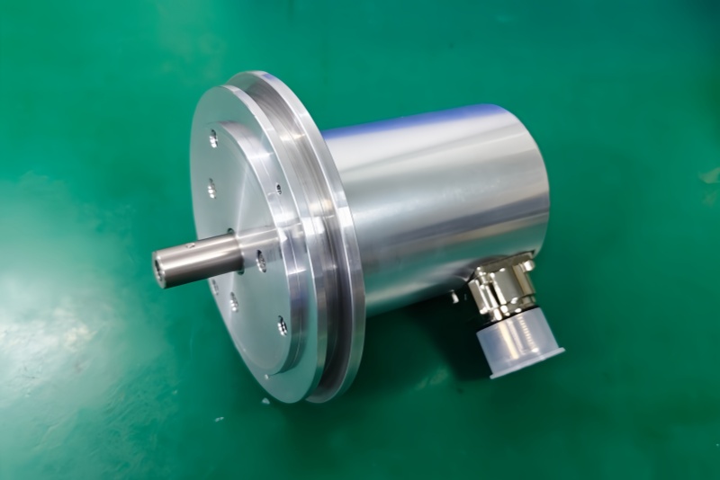
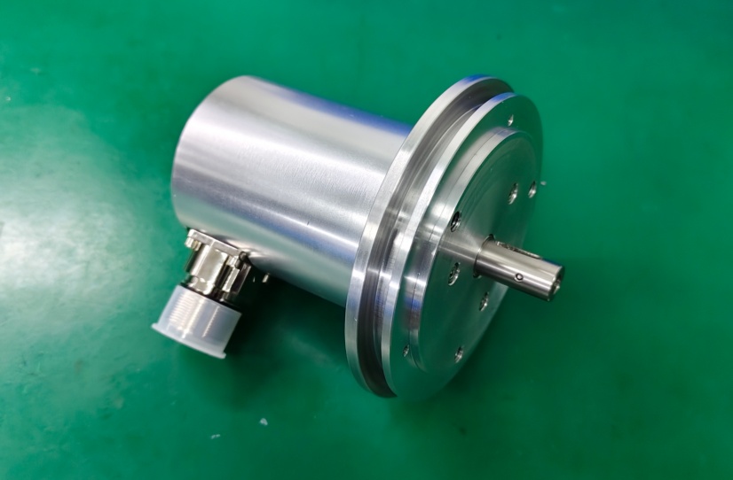
The drawing shows a ZB80 UNI flange, 12FL / 24 shaft, radial cable outlet, and separate 15-pin and 25-pin SUB-D connectors. The larger flange helps mechanical mounting, but the connector system remains the practical failure point. A loose SUB-D shell, weak shield path, or strained cable can create intermittent bit errors before any encoder hardware fault appears.
The protection level is IP54, so the connector and cable side should not be treated as washdown-safe. In damp, oily, dusty, or high-EMC cabinets, the first fault normally appears at the connector and shielding layer.
Installation Notes
- Keep the model format as CEV65M-10964
- Map O_D0–O_D19 before checking anything else
- Confirm latch timing at the controller input
- Verify Preset1 logic before startup
- Keep the 25-pin SUB-D for output logic and the 15-pin SUB-D for programming logic clearly separated
- Do not mix RS485 programming lines with parallel data wiring
- Keep SUB-D shielding and cable strain relief solid
- De-energize the system before wiring or connector work
Key Data
- Model: CEV65M-10964
- Type: Absolute rotary encoder
- Interface: Parallel push-pull
- Code: Programmable
- Resolution: 2048 steps / revolution
- Multiturn range: 4096 revolutions
- Supply voltage: 11–27 VDC
- Output level: 11–27 VDC
- Flange: ZB80 UNI
- Shaft: 12FL / 24
- Connector: SUB-D 15-pin + SUB-D 25-pin
- Connector position: PG radial
- Cable length: 0.5 m
- Protection: IP54
- Temperature range: -20 °C to +70 °C
- Options: Latch, Preset 1, Programmable
- Pinout: STK129A
- Parameter file: CEV65M-10964
- Firmware: 437865