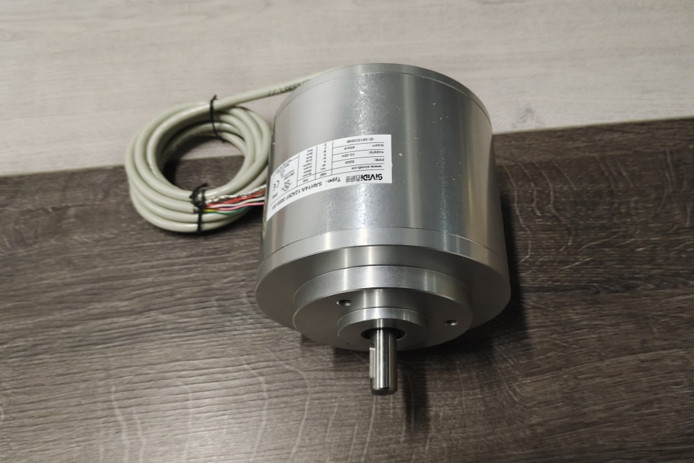
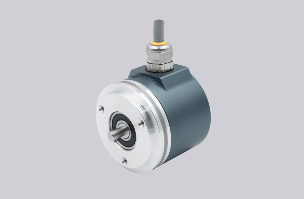
EncoderWorks can configure OCD-EEC1B-1216-C12S-PCM as a custom compatible replacement solution for absolute multiturn EtherNet/IP feedback where IP address, CIP data behavior, DLR continuity, 28-bit position structure, and Ø12 mm solid-shaft clamp-flange fit must remain aligned with the installed PLC project. The failure boundary is not only the 10–30 VDC supply, but also Ethernet port mapping, device identity, configuration assembly, preset behavior, direction logic, power reference, and coupling alignment. Typical production lead time: 15 working days.
This model is used where the control system reads absolute multiturn position over an EtherNet/IP network instead of Profibus data, discrete parallel wires, or incremental A/B/Z pulses. A compatible replacement must preserve the 16-bit singleturn and 12-bit multiturn position structure, Binary position handling inside the device, CIP communication behavior, DLR ring function, IP-address setting method, radial M12 connector layout, and Ø12 mm solid-shaft mechanical interface.


System Limits
The first system boundary is the EtherNet/IP network and PLC configuration. OCD-EEC1B-1216-C12S-PCM uses CIP communication with position, velocity, acceleration, and temperature-related device data, so the PLC project must see the same network identity, IP address behavior, process-data expectation, configuration assembly, preset function, counting direction, round-axis setting, and diagnostic response. If the replacement is installed with a wrong IP address, incompatible configuration file, different data length, mismatched preset behavior, or changed direction logic, the network may detect a device while the axis reports wrong position, wrong direction, missing status data, or unstable commissioning results.
The second boundary is DLR continuity and Ethernet physical wiring. The two D-coded Ethernet ports, Tx/Rx pairing, shield continuity, power connector reference, GND integrity, and ring topology must match the installed machine. A correct encoder can still fail if the DLR path is broken, the wrong Ethernet port role is assumed, shield continuity is poor, the power reference is unstable, or the radial connector stack is stressed by nearby guarding or cable routing.
Wiring & Installation
Before replacement, confirm the full installed model code, EtherNet/IP IP address requirement, device identity expectation, configuration file, CIP assembly layout, preset requirement, counting direction, round-axis use, velocity and diagnostic data use, DLR topology, Ethernet port mapping, and 10–30 VDC power wiring. Do not treat this as a Profibus, Bit Parallel, or incremental replacement, because the controller is reading a configured Ethernet device rather than a fieldbus node, separate data bits, or an A/B/Z pulse train.
The solid-shaft installation must also be checked carefully. The Ø12 mm single-flat shaft, 20 mm shaft length, clamp flange, coupling type, shaft insertion depth, radial connector clearance, axial load, radial load, and alignment accuracy can affect long-term stability. Poor coupling alignment, excessive side load, cable strain, connector stress, or grounding discontinuity can cause mechanical drift, communication faults, intermittent diagnostics, or early bearing wear.
Custom Compatible Solution
- Match EtherNet/IP device behavior, 16-bit singleturn plus 12-bit multiturn feedback, CIP data expectations, and IP-address requirement
- Preserve DLR continuity, D-coded Ethernet Tx/Rx mapping, A-coded power wiring, GND reference, and shield continuity
- Adapt the Ø12 mm solid shaft, 20 mm shaft length, 58 mm C clamp-flange class, radial connector layout, and mechanical mounting boundary
- Review configuration-file compatibility, preset direction, round-axis parameters, diagnostic data, connector clearance, and shaft coupling alignment before shipment
Key Data
| Item | Data |
|---|---|
| Model | OCD-EEC1B-1216-C12S-PCM |
| Encoder type | Absolute multiturn rotary encoder |
| Interface | EtherNet/IP |
| Profile | CIP |
| Transmission rate | 100 Mbit |
| Interface cycle time | ≥ 1 ms |
| Supply voltage | 10–30 VDC |
| Output driver | Ethernet |
| Sensor technology | Optical |
| Singleturn resolution | 16 bit |
| Multiturn resolution | 12 bit |
| Total position structure | 28-bit absolute multiturn data |
| Code | Binary |
| Multiturn technology | Mechanical gearing, no battery |
| Network functions | Boot-loader, Round Axis, DLR, velocity, acceleration, temperature values |
| Programming functions | Resolution, velocity time base/filter, preset, counting direction, parameter control priority, IP address |
| Connection | 2 × M12 D-coded Ethernet + 1 × M12 A-coded power |
| Connection orientation | Radial + rotary switches + M25 |
| Shaft / flange | Solid shaft, single flat, Ø12 mm × 20 mm, 58 mm C clamp flange class |
| Protection class | IP66 / IP67 boundary requires confirmation against installed version |
| Key replacement checks | IP address, CIP assembly, DLR continuity, Ethernet Tx/Rx mapping, power reference, preset, direction, 28-bit position structure, Ø12 mm solid-shaft coupling fit |