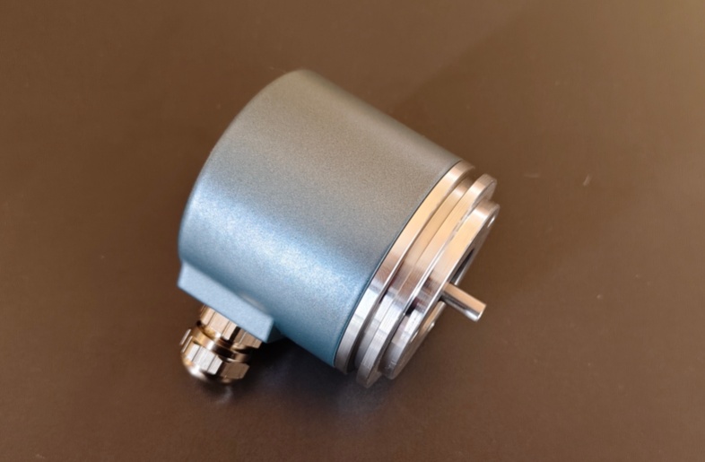
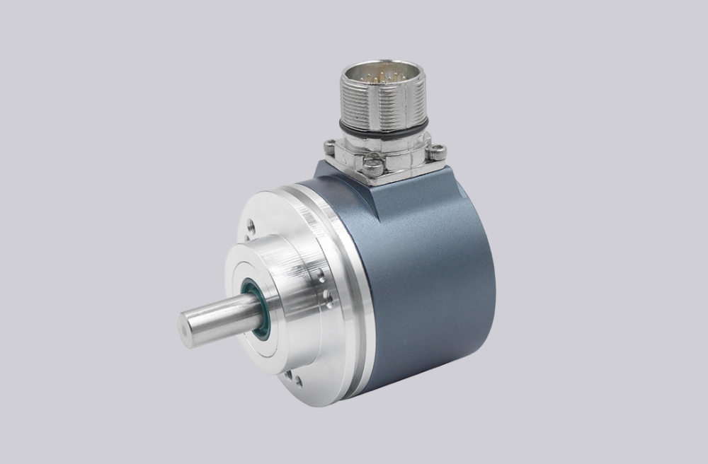
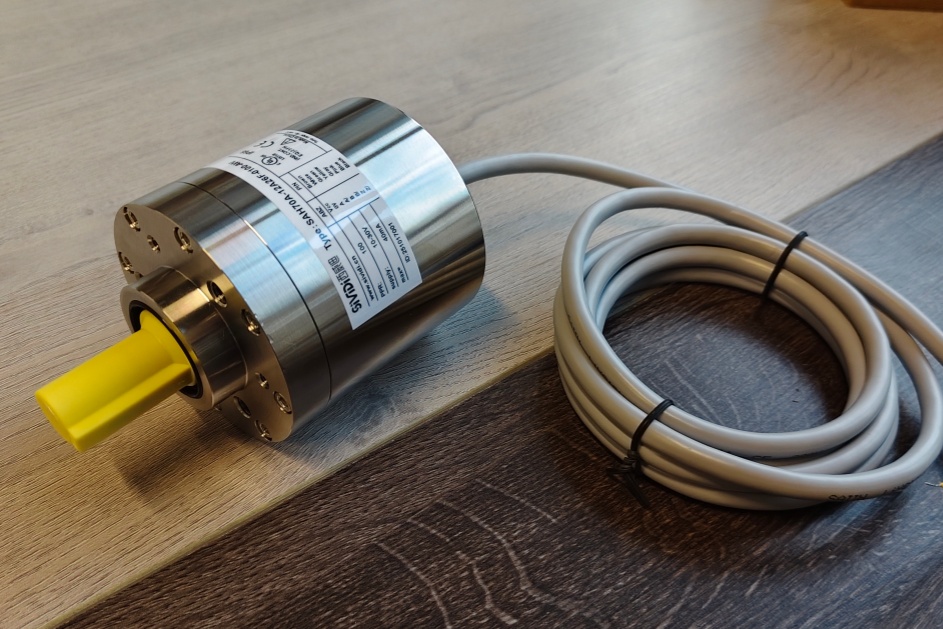
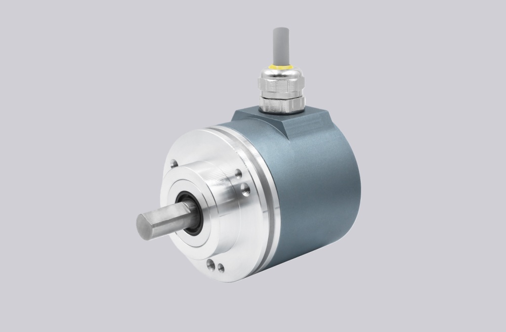
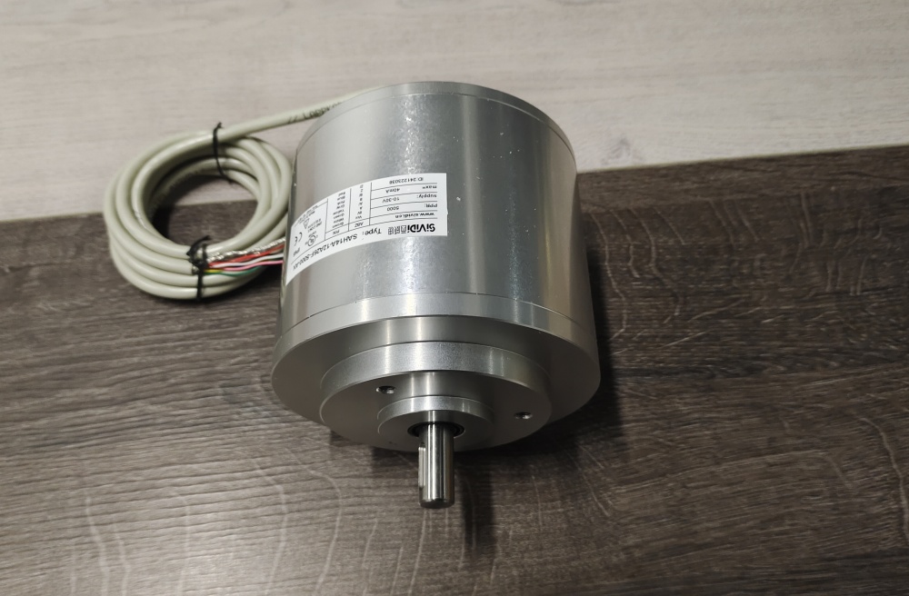
A custom compatible replacement for FVS58N-011ADR3GN-0013 can be supplied by EncoderWorks with the main check placed on Gray-code pin mapping, radial AD connector assignment, and Ø10 mm clamping-flange alignment. This model is different from the K2 cable version because the failure point moves from conductor tracing to the 19-pin connector interface. The connector may fit physically, but the controller still depends on the same 13-bit Gray word, V/R state, LATCH input, and PRESET behavior.
The FVS58N-011ADR3GN-0013 is a singleturn absolute encoder with fast parallel push-pull output, aluminum housing, 011 solid shaft with Ø10 mm x 20 mm clamping flange, AD 19-pin connector, radial exit direction, Gray code, and V/R, LATCH, PRESET inputs. The FVS58 series supports 13-bit singleturn absolute output, short-circuit-protected parallel signals, and code change frequency up to 400 kHz.
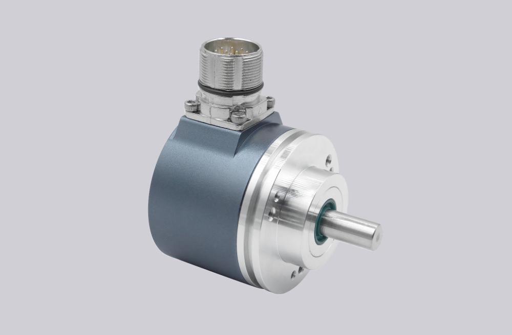
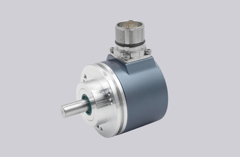
The first failure boundary is connector pin mapping. Data bit 1 through Data bit 13 must arrive at the same controller inputs as before. If one pin is shifted, or if the cabinet expects a different Gray bit order, the encoder can output a stable signal while the PLC decodes the wrong angle. The AD plug reduces field wiring work, but it does not remove the need to verify every data bit and control input.
This replacement fails when the 19-pin connector locks correctly and all Gray outputs toggle, but the machine position is wrong because pin assignment, bit order, or LATCH wiring does not match the original encoder. The hardware looks compatible, while the absolute word is not.
The second boundary is input-state control. V/R changes the counting direction, LATCH freezes the position word for stable readout, and PRESET sets the output word to zero. The FVS58 connection table separates these inputs from data outputs, so they should not be treated as unused pins or optional signals.
Mechanically, the Ø10 mm clamping-flange shaft must be coupled without side load. Coupling eccentricity or uneven flange seating can transfer radial or axial force into the encoder. The datasheet lists shaft-load limits, but those limits are not installation targets.
The replacement decision should first confirm 011 clamping-flange geometry, coupling alignment, radial AD connector clearance, 13-bit Gray pin order, V/R direction logic, LATCH timing, PRESET behavior, supply voltage, shielding, and controller input thresholds. EncoderWorks treats FVS58N-011ADR3GN-0013 as an industrial encoder custom compatible solution where connector mapping and flange mechanics decide field reliability.
Typical production lead time: 15 working days.
Key Data
| Item | Data |
|---|---|
| Model | FVS58N-011ADR3GN-0013 |
| Encoder type | Singleturn absolute encoder |
| Interface | Fast parallel push-pull |
| Housing | Ø58 mm aluminum housing |
| Shaft version | Solid shaft |
| Shaft / flange | 011, Ø10 mm x 20 mm with clamping flange |
| Connection | AD 19-pin connector |
| Exit direction | Radial |
| Output code | Gray code |
| Resolution | 13-bit singleturn / 8192 steps |
| Operating voltage | 10–30 VDC |
| Code change frequency | Up to 400 kHz |
| Inputs | V/R, LATCH, PRESET |
| Main engineering anchor | Gray pin mapping and clamping flange |
| Main failure boundary | Wrong Gray pin order, LATCH error, PRESET fault, coupling preload |