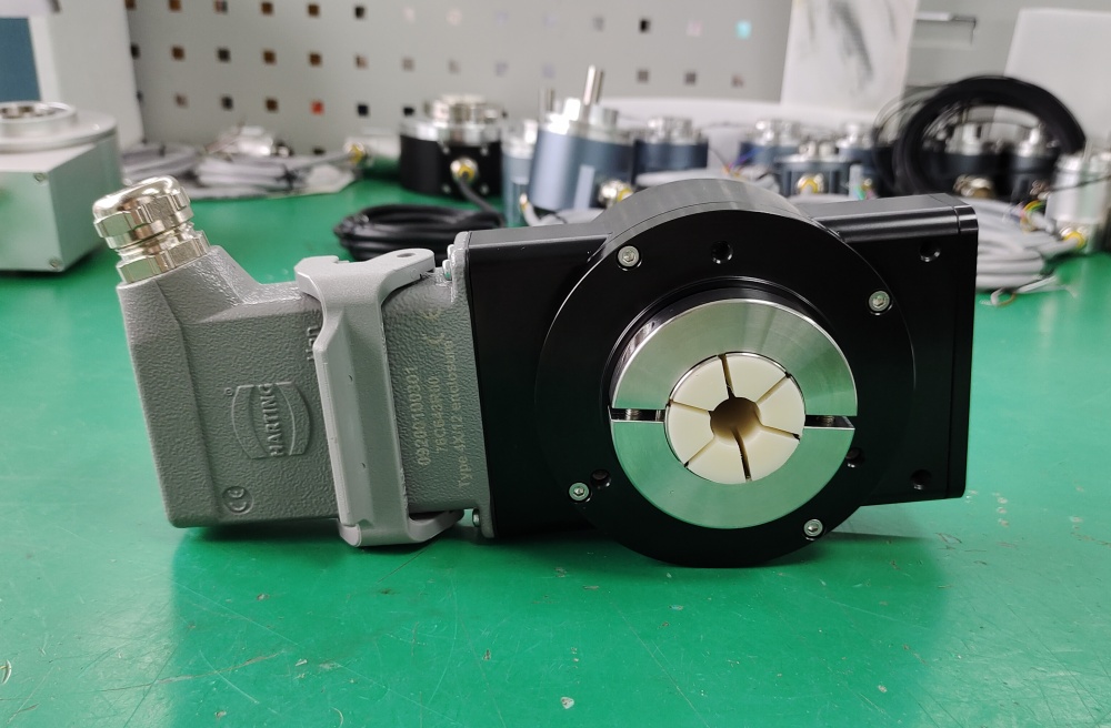
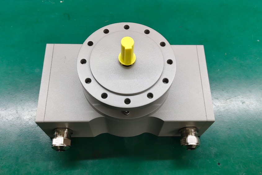
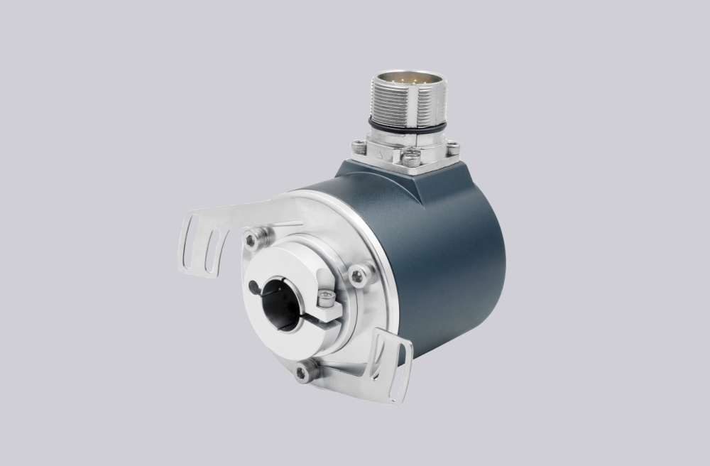
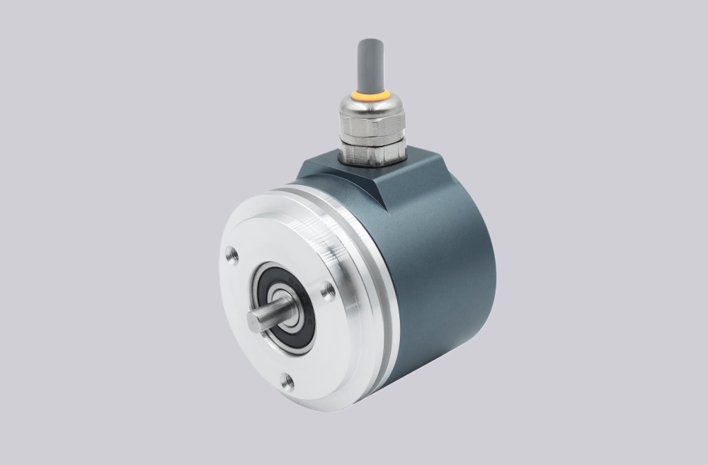
EncoderWorks develops a custom compatible replacement solution for DAB58-M360WA01 focused on preserving 0–20 mA analog angle feedback, 12-bit output scaling, zero-point adjustment behavior, measuring-range configuration, CW/CCW signal sense, multifunction input settings, and industrial wiring compatibility. The replacement boundary is not only mechanical replacement, but also current-output accuracy, analog reference stability, parameter adjustment logic, power supply compatibility, and controller-side scaling consistency. Typical production lead time: 15 working days.
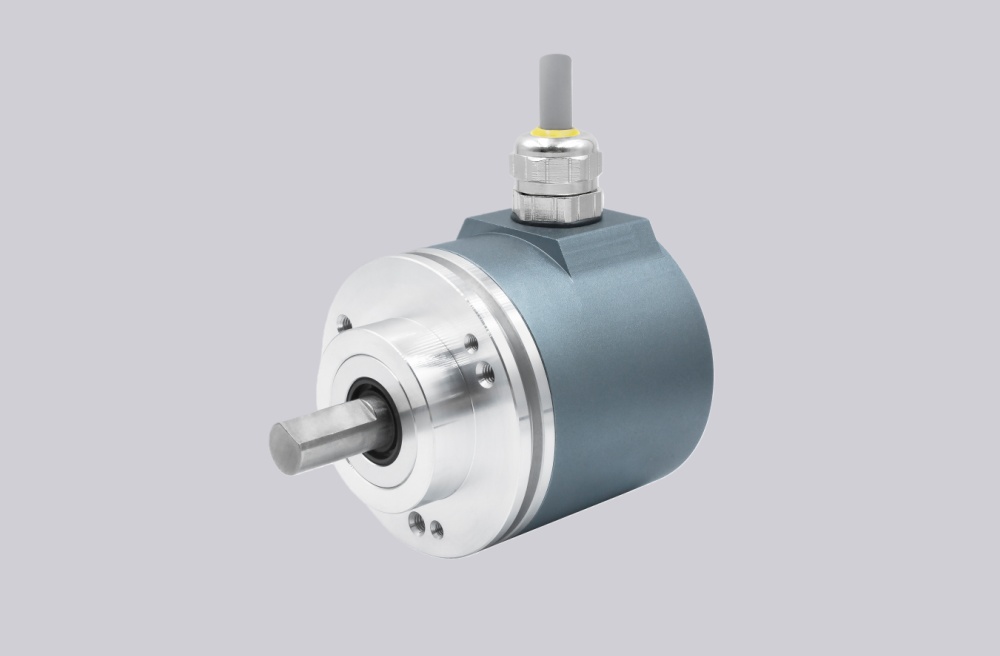
DAB58-M360WA01 is designed for angle measurement systems where the controller interprets position through an analog current signal rather than a digital communication interface. A compatible replacement must preserve the 0–20 mA output relationship, 360° measurement range, adjustable zero position, adjustable measuring range, output direction behavior, and the original electrical reference structure.
System Limits
The first system boundary is the analog current output. The controller does not read encoder counts directly but evaluates the relationship between mechanical angle and output current. A replacement must maintain the programmed current range, zero position, signal direction, and output stability. Incorrect scaling can cause the controller to receive a valid current signal while calculating an incorrect mechanical position.
The second boundary is the analog reference and configuration input structure. The output common, supply reference, multifunction inputs, and adjustment logic must remain compatible with the installed system. Incorrect zero-point adjustment, measuring-range configuration, or CW/CCW direction setting can shift the entire measurement relationship even when the analog output remains within the expected current range.
Wiring & Installation
Before replacement, confirm the complete installed configuration including 0–20 mA output requirement, supply voltage, analog common reference, zero-point setting, measuring range, output direction, multifunction input usage, connector assignment, cable shielding, and installation environment.
The analog signal wiring should maintain a stable reference potential between the sensor output and controller input. Cable routing should avoid high-current switching equipment, motor cables, and electromagnetic interference sources. Poor grounding or unstable supply reference may appear as signal drift, unstable position feedback, or incorrect zero-point behavior.
During installation, verify the programmed parameters before commissioning. If the application requires a special measuring range or zero-point offset, these settings must be reproduced rather than using default adjustment values.
Custom Compatible Solution
- Match 0–20 mA analog angle feedback, 12-bit output behavior, and controller scaling requirements
- Preserve zero-point adjustment, measuring-range setting, CW/CCW output direction, and multifunction input logic
- Adapt Binder Series 723 connector wiring, supply reference, analog common, and shielding requirements
- Validate current output stability, parameter configuration, grounding, and commissioning values before shipment
Key Data
| Item | Data |
|---|---|
| Model | DAB58-M360WA01 |
| Sensor type | Analog angle transducer |
| Output signal | 0–20 mA current output |
| Resolution | 12-bit analog output |
| Measurement range | 360° standard configuration |
| Output scaling | 20 mA per 360° |
| Direction setting | CW / CCW programmable |
| Adjustment functions | Zero point and measuring range adjustment |
| Interface | Binder Series 723 connector |
| Supply voltage | 20–26 VDC |
| Signal reference | Analog common 0V |
| Configuration input | Multifunction inputs MFP |
| Main replacement focus | Current scaling, zero position, range setting, wiring continuity |
| Application check | Controller input scaling, grounding, shielding, programmed values |