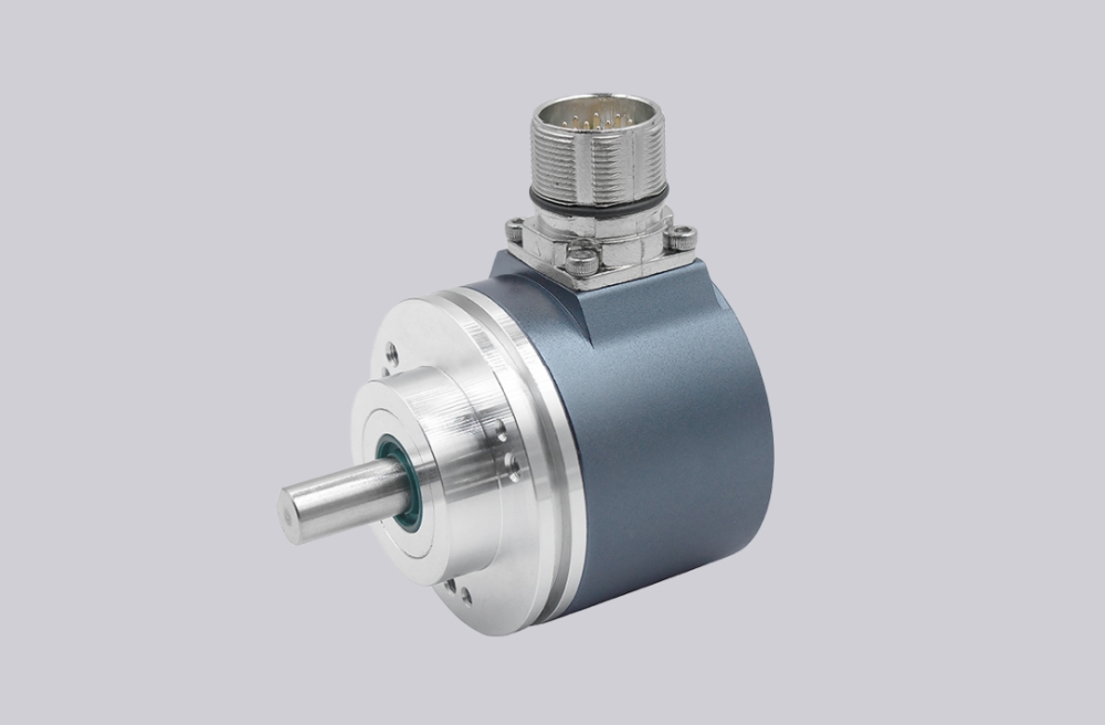
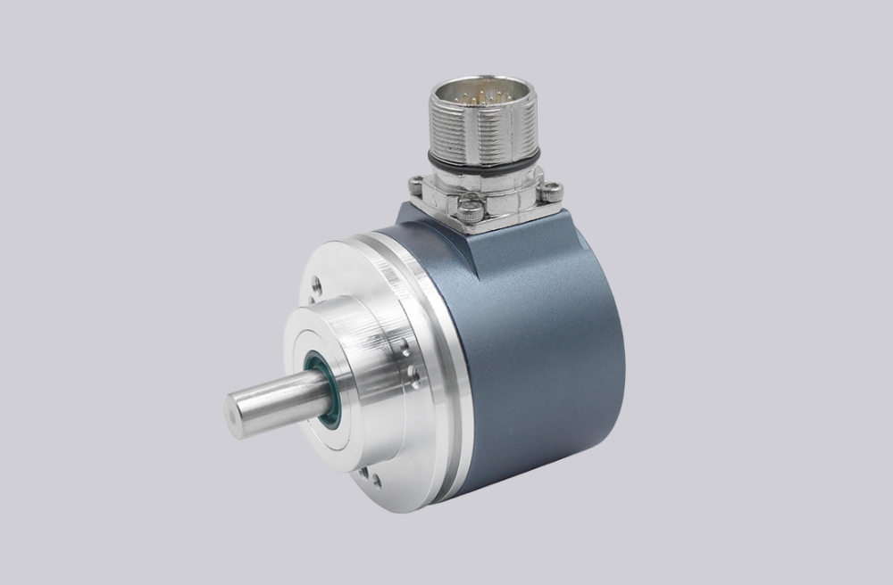
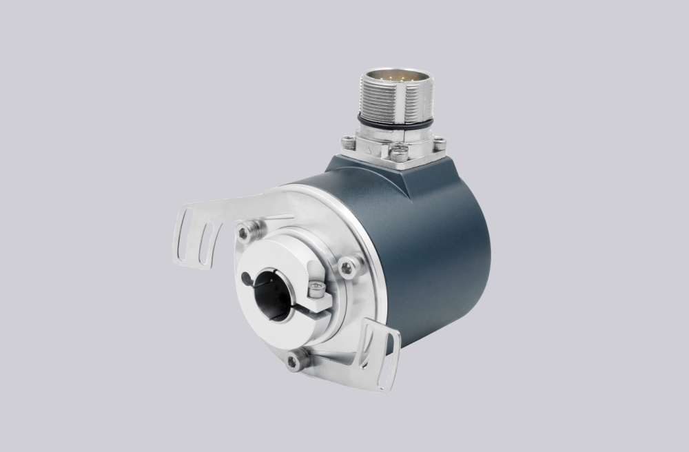
EncoderWorks develops custom compatible replacement solutions for DAB65-S360WC01 and DAB65-S360CA01 focused on preserving analog angle feedback, adjustable zero-point configuration, measurement-range settings, CW/CCW output direction, M16 connector wiring, supply reference stability, and controller-side scaling compatibility. The replacement boundary is not only mechanical installation, but also analog signal accuracy, output scaling consistency, parameter adjustment logic, grounding reference, and system commissioning stability. Typical production lead time: 15 working days.
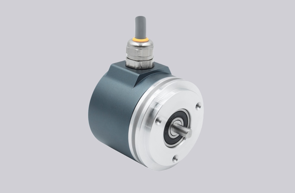
DAB65-S360WC01 and DAB65-S360CA01 belong to the same adjustable angle transducer platform. Both models provide analog position feedback with configurable signal direction, zero adjustment, and measuring-range adjustment. The main difference is the output interface: DAB65-S360WC01 uses a 0–20 mA current output, while DAB65-S360CA01 provides a 0–10 V voltage output. A compatible replacement must preserve the controller input type, signal scaling relationship, adjustment parameters, and original wiring structure.
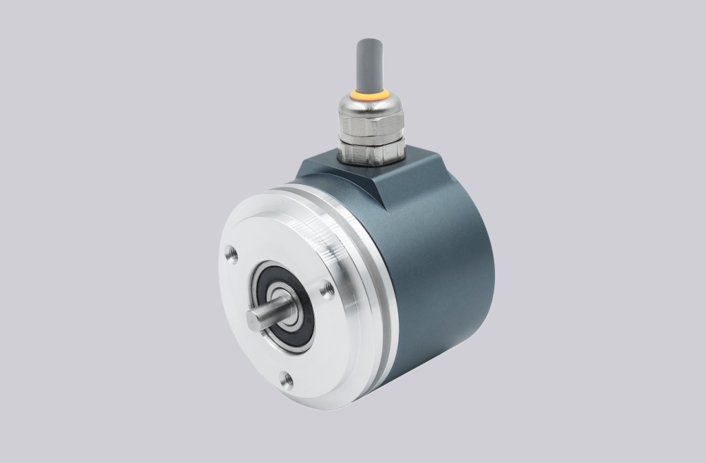
System Limits
The first system boundary is analog signal scaling. Unlike digital encoders that transmit discrete position data, these models represent angle position through a continuous analog output value. A replacement can appear electrically active while still producing incorrect machine position if the current or voltage scaling, zero point, measuring range, or signal direction does not match the controller configuration.
For the current-output version, the control system depends on stable 0–20 mA conversion. For the voltage-output version, the system depends on correct 0–10 V interpretation and input impedance compatibility. Incorrect selection between current and voltage interfaces may result in unstable position feedback, incorrect calibration, or limited measurement range.
The second boundary is the adjustment and reference system. Zero-point offset, measurement range, and CW/CCW signal sense must remain consistent with the original installation. Incorrect parameter adjustment can shift the complete output curve even when the analog signal remains within the expected range.
Wiring & Installation
Before replacement, confirm the complete installed configuration including output type (0–20 mA or 0–10 V), supply voltage, analog common reference, connector pin assignment, zero-point setting, measuring range, signal direction, cable shielding, and controller input specification.
The M16 connector wiring must be verified before commissioning. The analog reference potential should remain stable between the transducer and controller. Shield continuity and grounding quality should be checked when the device operates near motors, frequency converters, switching equipment, or other electromagnetic interference sources.
During installation, reproduce the programmed adjustment values rather than relying on factory defaults. If the application requires a special measurement range or zero offset, these parameters should be confirmed before the replacement unit enters service.
Custom Compatible Solution
- Match analog angle feedback requirements with correct 0–20 mA or 0–10 V output scaling
- Preserve zero-point adjustment, measurement-range configuration, and CW/CCW signal direction
- Maintain M16 connector wiring, supply reference, analog common, and shielding requirements
- Validate controller input compatibility, grounding stability, calibration parameters, and commissioning values before shipment
Key Data
| Item | Data |
|---|---|
| Models | DAB65-S360WC01 / DAB65-S360CA01 |
| Sensor type | Analog angle transducer |
| Measurement range | 360° standard configuration |
| Output WC01 | 0–20 mA current output |
| Output CA01 | 0–10 V voltage output |
| Adjustment functions | Zero point and measurement range |
| Signal direction | CW / CCW programmable |
| Connector | M16 circular connector, 4-pin |
| Supply voltage | 20–26 VDC |
| Operating temperature | -20°C … +60°C |
| Signal reference | Analog common 0V |
| Main replacement focus | Output scaling, calibration, wiring continuity |
| Key engineering checks | Controller input type, grounding, shielding, parameter settings |