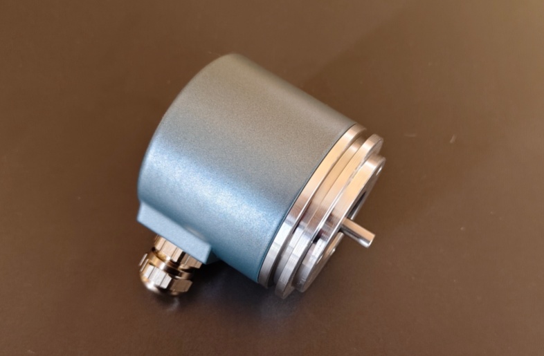
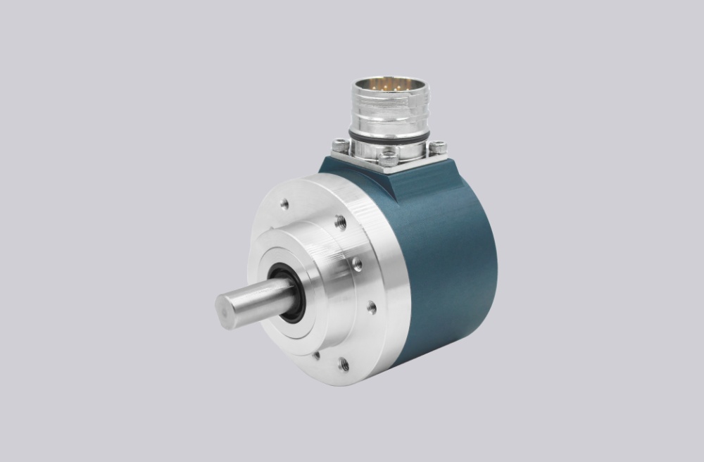
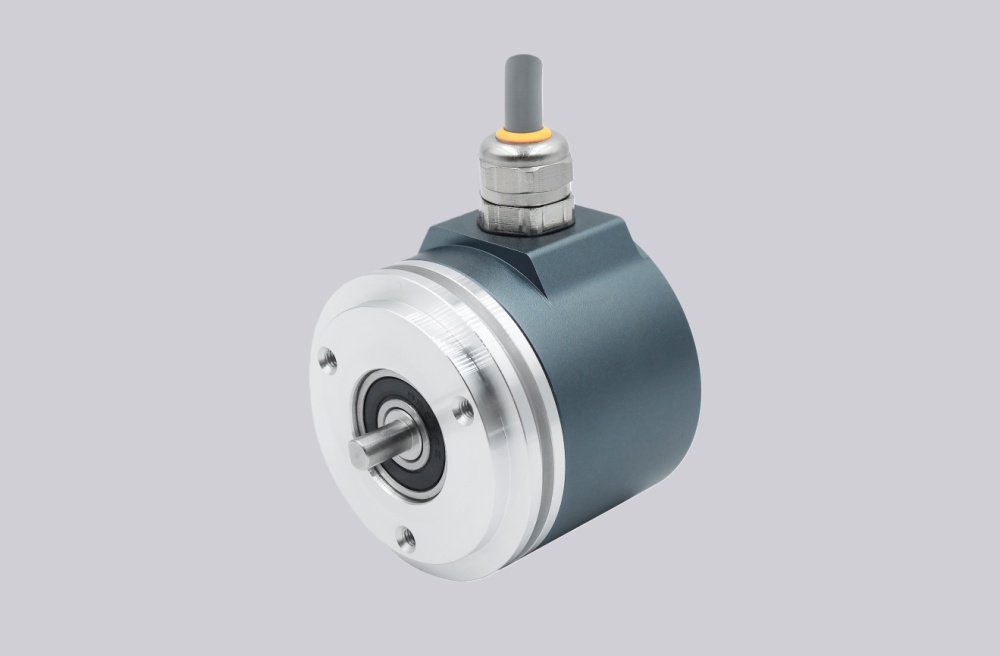
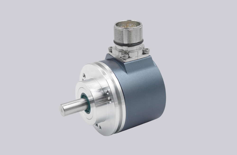
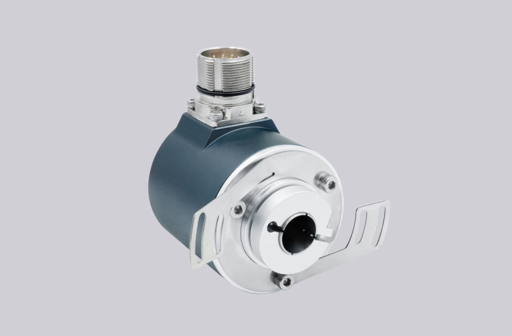
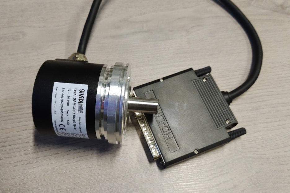
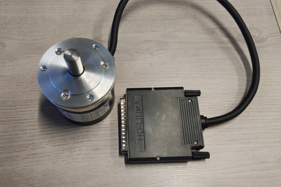
EncoderWorks develops a custom compatible replacement solution for CR65-1024G19C01 focused on preserving 19-bit Gray code output mapping, parallel data capture timing, D-sub 37-pin wiring continuity, latch control behavior, enable logic, CW/CCW code direction, and industrial installation requirements. The replacement boundary is not only resolution matching, but also correct bit assignment, controller latch timing, output supply separation, signal reference stability, and mechanical integration accuracy. Typical production lead time: 15 working days.
CR65-1024G19C01 is designed for absolute position feedback systems where the controller reads parallel Gray-coded position data instead of a serial communication protocol. A compatible replacement must preserve 1024 positions per revolution, 512-turn measurement range, 19-bit Gray output structure, latch input behavior, enable control logic, code-direction selection, and the original D-sub connector assignment.
System Limits
The first system boundary is the parallel Gray-code data path. The controller depends on correct Bit 1 to Bit 19 mapping, stable output transitions, and proper latch capture timing. A replacement can appear electrically active while still producing incorrect position values if any data bit is shifted, the Gray-code sequence is changed, the latch signal is not handled correctly, or the controller samples data outside the valid capture window.
The second boundary is the control input and power structure. The Latch, Enable, and Code Sense signals must maintain the same logic behavior as the installed system. The separate output supply requirement must also be preserved because incorrect supply reference, common signal potential, or grounding arrangement can create unstable parallel output recognition.
Wiring & Installation
Before replacement, confirm the complete installed configuration including 19-bit data mapping, Gray-code sequence, D-sub 37-pin assignment, latch timing, enable polarity, CW/CCW direction setting, output supply voltage, common reference potential, and machine-side mounting conditions.
The D-sub connector wiring should be verified before commissioning. Bit assignment errors may result in incorrect absolute position feedback even when the encoder powers up normally. Maintain a stable 0 V reference between input and output circuits, and verify the separate output supply path before connecting the controller.
During installation, avoid routing parallel data wiring close to high-current switching equipment. Shielding, grounding continuity, and cable separation should be checked when the encoder operates near motors, drives, or electromagnetic interference sources.
Custom Compatible Solution
- Match 19-bit Gray-code parallel output, Bit 1–Bit 19 mapping, and latch capture behavior
- Preserve D-sub 37-pin connector assignment, Enable control, Code Sense direction, and signal reference
- Adapt separate output supply requirements and controller-side input compatibility
- Validate Gray-code sequence, timing margin, grounding, shielding, and commissioning parameters before shipment
Key Data
| Item | Data |
|---|---|
| Model | CR65-1024G19C01 |
| Encoder type | Absolute parallel encoder |
| Output code | Gray code |
| Resolution | 1024 positions / 360° |
| Measurement range | 512 turns |
| Data output | 19-bit parallel position data |
| Interface | D-sub 37-pin connector |
| Data mapping | Bit 1–Bit 19 |
| Control inputs | Latch, Enable, Code Sense |
| Direction control | CW / CCW code sense |
| Supply voltage | VS 11–26 VDC |
| Output supply | VC 5–26 VDC separate supply |
| Main integration focus | Gray mapping, latch timing, connector continuity |
| Replacement boundary | Bit assignment, control logic, grounding, mechanical integration |