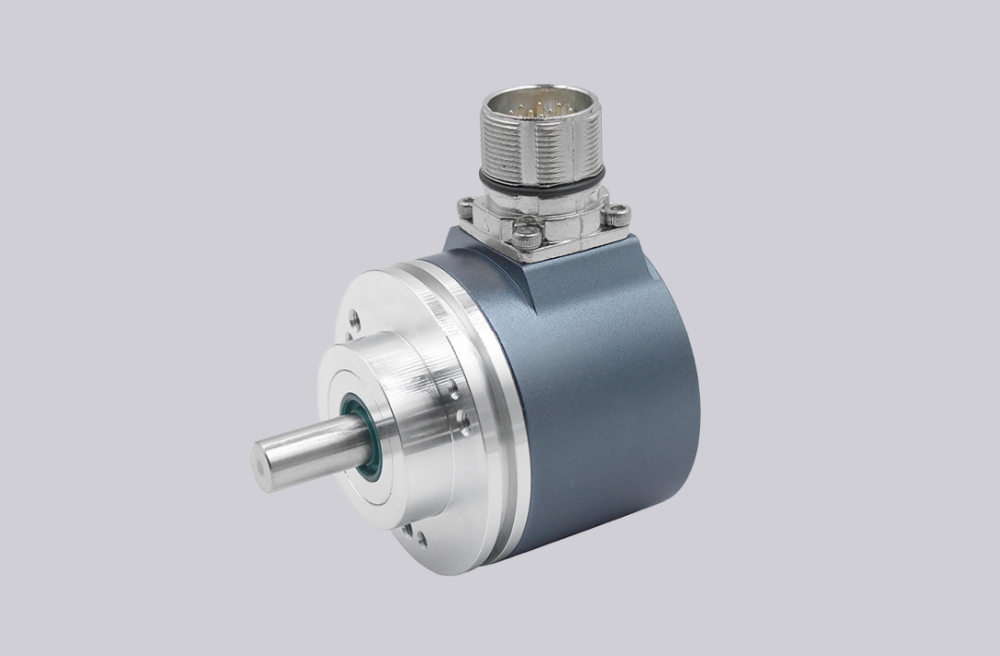
For the CEV65M-01429 encoder, we provide a custom compatible solution focused on parallel bit mapping, DataBus_disable control, latch timing, and SUB-D 37-pin connector stability. The main risk is not the absolute encoder core; it is whether the controller can read O_D0–O_D23 without bit shift, tristate output conflict, latch timing error, or preset-direction mismatch. Typical production lead time: 15 working days.
This is a parallel push-pull absolute encoder, not SSI, Profibus, PROFINET, CANopen, analog, or incremental feedback. The controller receives the position as a wide parallel word. If one data line is wrong, or if the DataBus_disable input forces the outputs into the wrong state, the machine may see a valid-looking but incorrect absolute value.
Where the System Fails First
The pinout defines O_D0 to O_D23 as data outputs, with DataBus_disable_IN, Preset1_IN, Preset2_IN, I_Latch, Direction IN, RS485 programming lines, supply voltage, and ground. This makes the integration risk very specific: the data word, latch signal, bus-disable logic, and preset inputs must all match the controller design.
The weak points are direct:
- Wrong O_D0–O_D23 mapping → corrupted absolute position
- DataBus_disable misuse → outputs forced to tristate
- Latch timing error → unstable sampled word
- Wrong Direction input → reversed counting logic
- Preset1 / Preset2 wiring error → false machine reference
- SUB-D shielding weakness → random bit-level noise
The document lists BUS, F/R, Latch, Preset 1+2, and Programmable options. These functions decide whether the PLC reads, freezes, disables, reverses, presets, and interprets the position word correctly. They should be checked before treating the encoder body as the first failure point.
Connector and Wiring Boundary
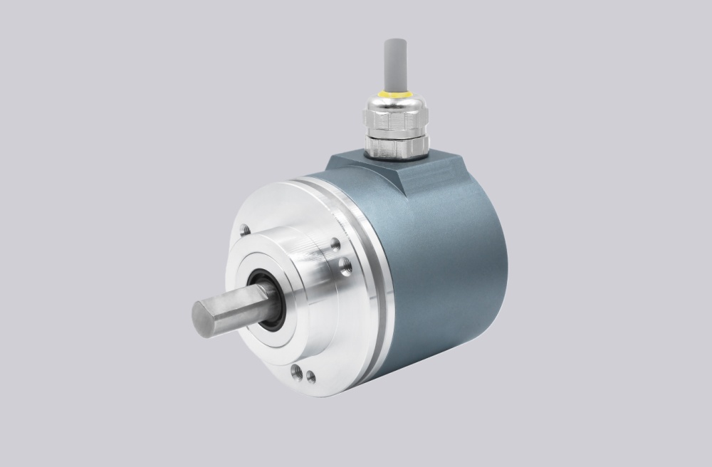
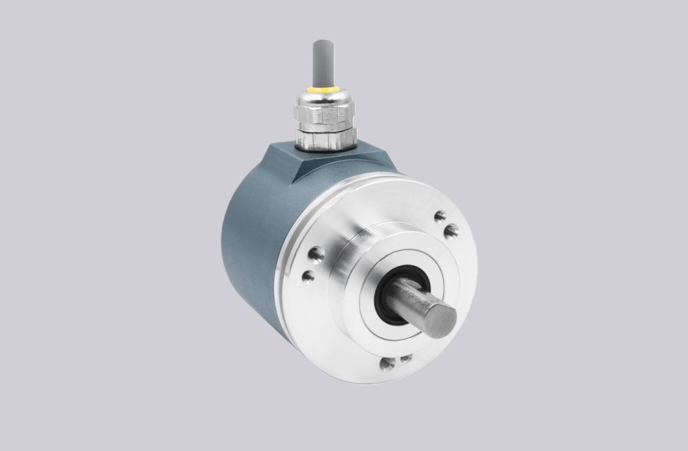
The drawing shows a ZB36 flange, 10FL / 19.5 shaft, 0.5 m cable, and 37-pin SUB-D connector with PG axial cable exit. The short cable reduces long-distance signal loss, but it does not remove cabinet-side EMC problems. Parallel push-pull outputs are sensitive to input reference, shield continuity, and connector strain.
The practical rule is simple: check the parallel bit map first, then DataBus_disable, then latch timing. Replacing the encoder without checking these three points often leaves the same fault in the machine.
Installation Notes
- Keep the model format as CEV65M-01429
- Map O_D0–O_D23 before replacing the encoder
- Confirm DataBus_disable_IN logic before startup
- Check I_Latch timing at the controller input
- Verify Direction, Preset1, and Preset2 logic
- Keep RS485 programming wires separate from data outputs
- Maintain SUB-D shielding and cable strain relief
- De-energize the system before wiring or connector work
Key Data
- Model: CEV65M-01429
- Type: Absolute rotary encoder
- Interface: Parallel push-pull
- Code: Programmable
- Resolution: 4096 steps / revolution
- Multiturn range: 4096 revolutions
- Supply voltage: 11–27 VDC
- Output level: 11–27 VDC
- Flange: ZB36
- Shaft: 10FL / 19.5
- Connector: SUB-D 37-pin
- Connector position: PG axial
- Cable length: 0.5 m
- Protection: IP65
- Temperature range: -20 °C to +70 °C
- Options: BUS, F/R, Latch, Preset 1+2, Programmable
- Pinout: ST2227A
- Parameter file: CE833-265
- Firmware: 437865