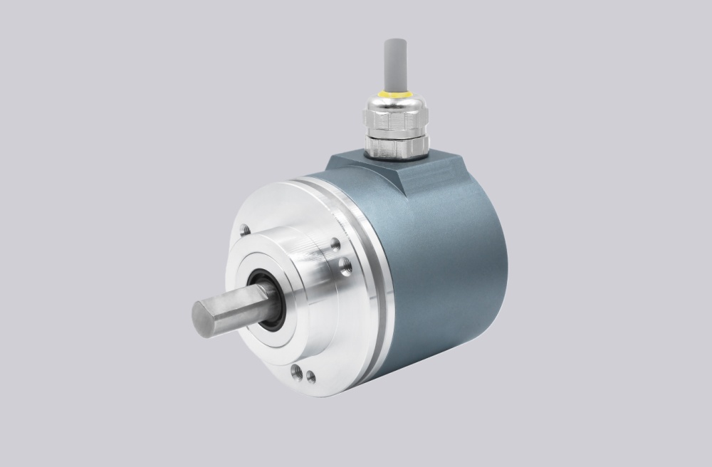
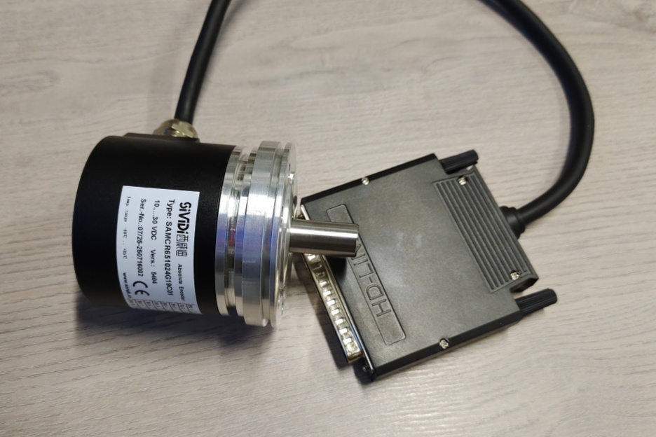
For CES582M-10044, also referenced as CES58M-00044, EncoderWorks can provide a custom compatible replacement solution for Profibus DP absolute multiturn feedback systems where the key checks are bus parameterization, 8192/4096 position scaling, D12H7 blind-shaft fit, and radial cable-gland wiring. The replacement must be verified at the PLC side, because a mechanically similar encoder can still fail if the GSD file, station address, termination, or multiturn scaling does not match the installed Profibus project. Typical production lead time: 15 working days.
This encoder is used where the controller reads absolute position through Profibus DP and expects the position value to remain valid across many revolutions. Replacement work should therefore treat the encoder as a complete fieldbus and mechanical feedback unit. The PLC configuration, station address, Profibus IN/OUT wiring, binary code reading, preset behavior, torque-support mounting, blind-shaft engagement, and cable-gland shield path must all be checked before the machine returns to service.
System Limits
The main system limit is Profibus DP parameterization. The controller may depend on a specific GSD file, station address, number of steps per revolution, number of revolutions, preset range, and diagnostic behavior. If these settings are not matched, the encoder may show a bus fault, stay outside data exchange, or return a position value with the wrong travel scale.
The second limit is bus termination and segment wiring. The connection cap uses separate Profibus IN and Profibus OUT terminals, and the terminal resistor must only be enabled when the encoder is the last station in the segment. Incorrect termination, swapped Data A/Data B, or weak shield continuity can create intermittent bus faults during drive operation.
The mechanical limit is the D12H7 blind shaft and DMS torque-support mounting. The blind shaft must be clamped without radial preload, while the torque support must prevent housing rotation without forcing the bearing system. Cable routing should also respect the radial cable-gland layout and bending radius.
Wiring & Installation
Before removing the existing encoder, record the Profibus station address, termination switch position, PLC hardware configuration, bus-in and bus-out wiring, supply polarity, shield connection, and mechanical zero position. The replacement should be checked against the controller project before startup.
After installation, confirm that the encoder enters cyclic data exchange, reports stable diagnostics, and returns the expected absolute position. Then test preset, counting direction, and multiturn travel across more than one shaft revolution.
Custom Compatible Solution
EncoderWorks can configure the replacement around the installed Profibus system:
- Match Profibus DP communication, station address behavior, GSD configuration, and diagnostic response
- Verify 8192 steps per revolution, 4096 revolutions, binary code reading, preset, and direction behavior
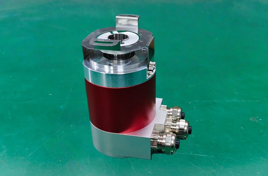
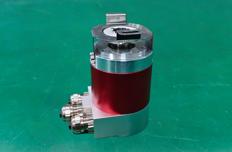
- Adapt the D12H7 blind shaft, DMS torque-support mounting, radial cable-gland connection, and housing format
- Review bus termination, shield grounding, cable routing, and shaft clamping load for stable operation
Key Data
| Item | Data |
|---|---|
| Model | CES582M-10044 |
| Alternative reference | CES58M-00044 |
| Encoder type | Absolute multiturn encoder |
| Interface | Profibus DP |
| Resolution | 8192 steps/rev × 4096 revolutions |
| Code | Binary |
| Supply voltage | 10–30 VDC |
| Protection class | IP65 |
| Operating temperature | -20°C to +75°C |
| Shaft | D12H7 blind shaft |
| Flange / mounting | DMS torque support, pitch circle 63 |
| Connection | Radial cable gland, 1× M12 + 2× M16 |
| Pinout | TR-ECE-TI-GB-0065 |
| Approval | UL USA + Canada |