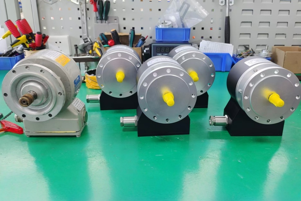
For AMG11P13Z0, EncoderWorks can provide a custom compatible replacement solution for Profibus DP absolute feedback systems where the key checks are node addressing, GSD configuration, 13-bit position scaling, and ø11 mm solid-shaft alignment. The replacement must be verified from the PLC side, because a mechanically similar encoder can still fail if the Profibus address, preset value, direction setting, or scaling parameter does not match the existing project. Typical production lead time: 15 working days.
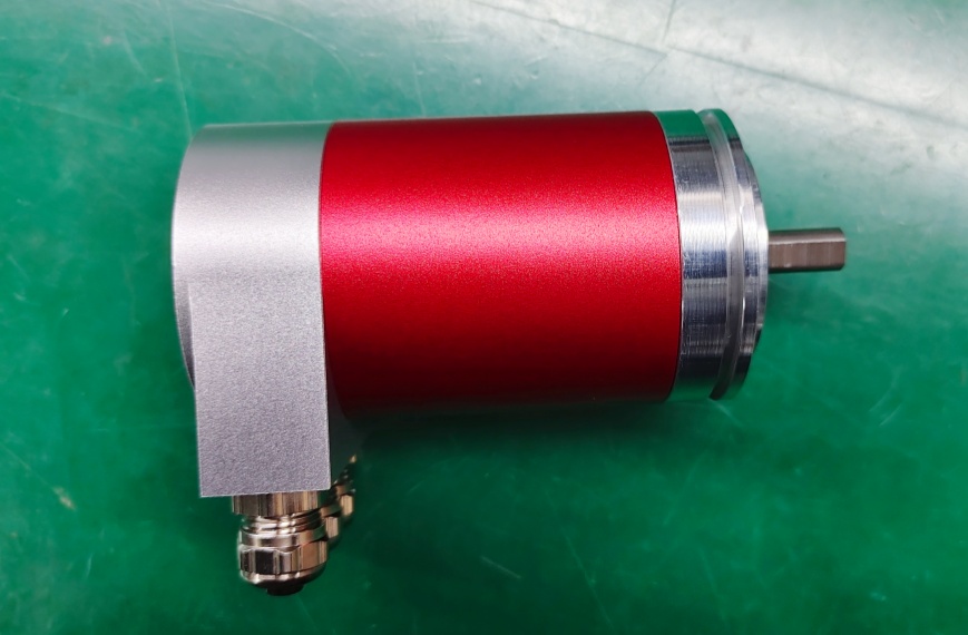
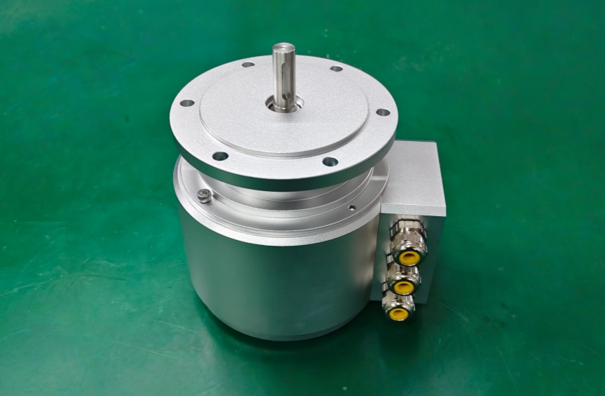
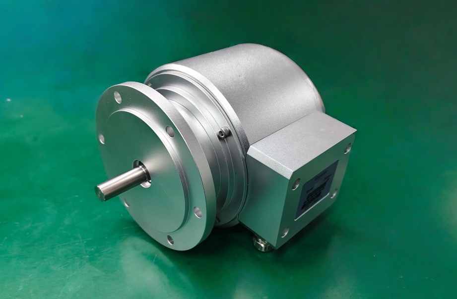
This model belongs to the AMG 11 absolute encoder series with EURO flange B10 and ø11 mm solid shaft. In the AMG11P13Z0 configuration, the interface is Profibus and the absolute position share is 13-bit singleturn, without additional incremental output. Replacement work should therefore focus on fieldbus configuration, singleturn scaling, mechanical coupling, and shielded bus wiring rather than incremental signal matching.
System Limits
The main system limit is Profibus DP parameterization. The PLC may depend on a fixed device address, GSD file, preset value, rotating direction, diagnostic response, and scaling setting. If one of these values is different, the encoder may enter the network but return an incorrect position value or report a parameter error.
The second limit is 13-bit singleturn interpretation. The controller must read the position as 8192 steps per revolution. If the scaling or direction parameter is wrong, the value may look stable but move in the wrong direction or no longer match the machine zero point.
The mechanical limit is the ø11 mm solid shaft and EURO flange B10 fit. The coupling must be aligned without radial force, axial preload, or flange distortion. Shield grounding and Profibus cable routing should also be checked, especially near inverter, motor, brake, or contactor wiring.
Wiring & Installation
Before removing the existing encoder, record the Profibus address, PLC hardware configuration, GSD file version, preset value, direction parameter, supply voltage, shield connection, and mechanical zero position. The replacement should be checked against the controller project before startup.
After installation, confirm that the encoder enters cyclic data exchange, reports stable diagnostics, and returns the expected 13-bit position value. Then test preset, direction, and one full shaft revolution from the PLC display.
Custom Compatible Solution
EncoderWorks can configure the replacement around the installed Profibus system:
- Match Profibus DP communication, device address behavior, GSD configuration, and diagnostic response
- Verify 13-bit singleturn scaling, preset, rotating direction, and PLC-side value trend
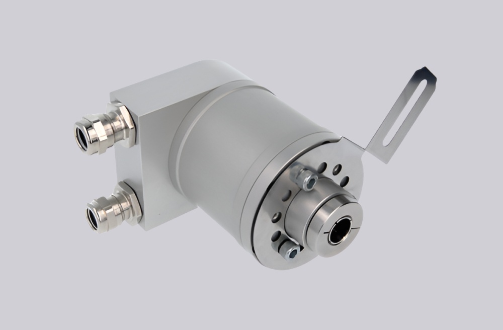
- Adapt the EURO flange B10, ø11 mm solid shaft, bus cover, and mechanical mounting requirement
- Review bus termination, shield grounding, cable routing, and shaft coupling load for stable operation
Key Data
| Item | Data |
|---|---|
| Model | AMG11P13Z0 |
| Encoder type | Absolute singleturn encoder |
| Interface | Profibus-DPV0 |
| Resolution | 13 bit singleturn / 8192 steps per revolution |
| Additional output | Without incremental output |
| Supply voltage | 9–30 VDC |
| Sensing method | Optical |
| Flange | EURO flange B10 |
| Shaft | ø11 mm solid shaft |
| Protection class | IP67 |
| Operating speed | ≤3500 rpm mechanical |
| Connection | Bus cover |
| Approval | CE / UL |