We developed a custom solution for the CEW65M-01983 wire draw encoder, intended for systems where linear position feedback over Profibus-DP must remain stable under continuous motion, industrial vibration, and long-travel mechanical operation. This configuration combines a CEW65M pull-rope measuring mechanism with a 4096 × 4096 multiturn absolute encoder, using PROFIBUS-DP Class 2, RS485 transmission, and a stainless steel measuring cable system. It is not a standard rotary encoder. It is a linear displacement measurement system where rope mechanics, spring stability, Profibus topology, and RS485 integrity determine whether the position data remains usable. Typical production lead time: 15 working days.
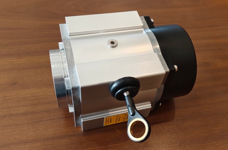
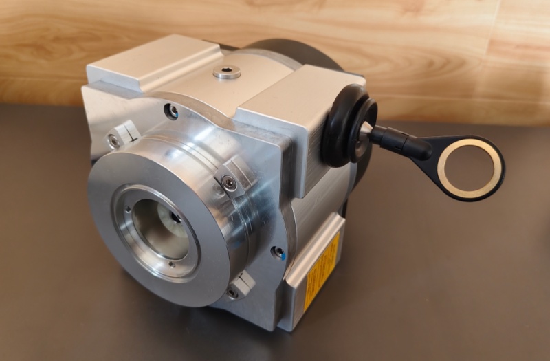
Custom Solution Photos
Stable operation depends on rope alignment, spring return stability, mounting rigidity, shielding continuity, and correct Profibus termination.
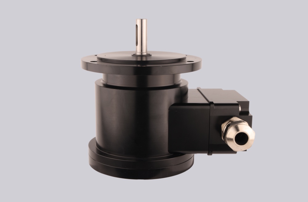
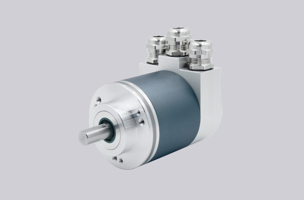
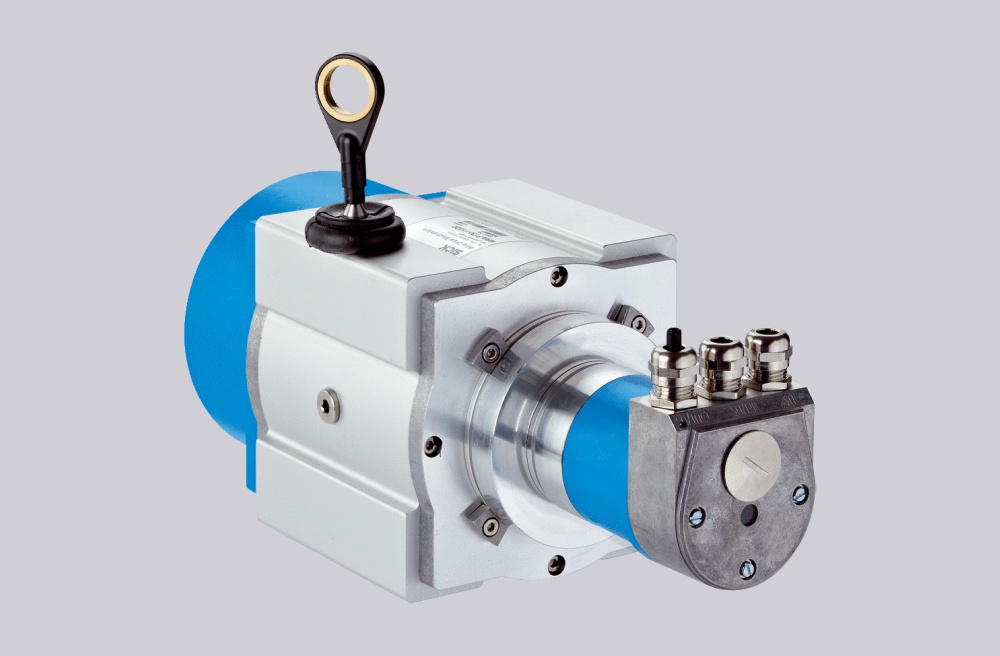
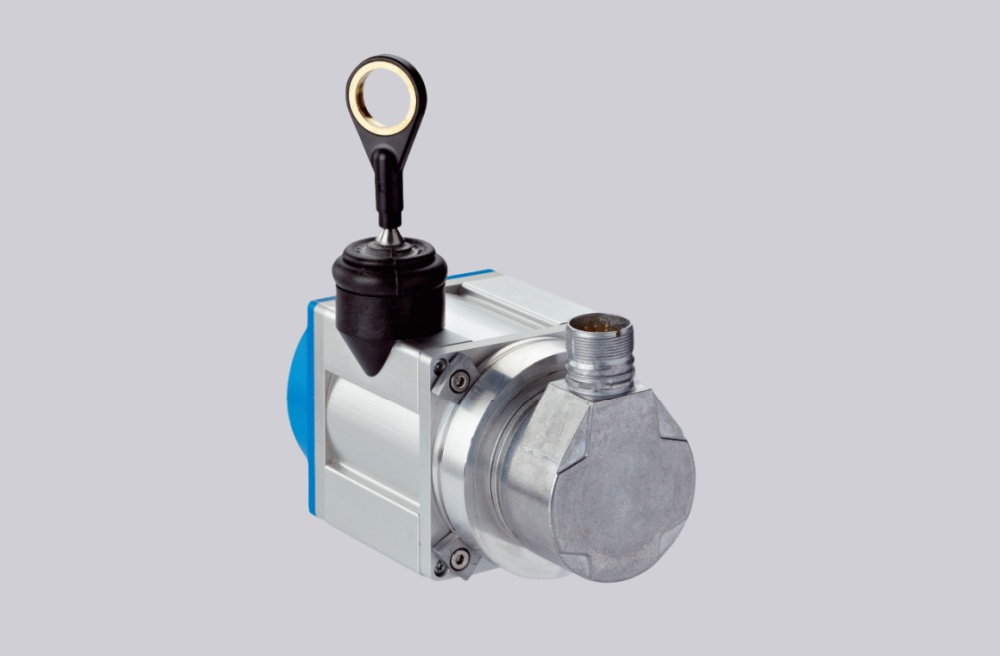
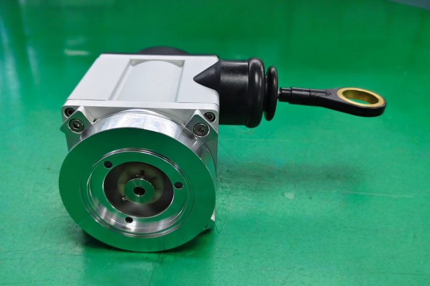
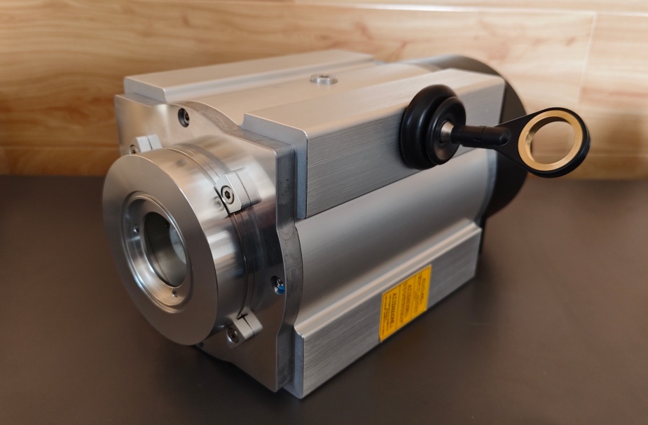
The drawing shows:
- stainless steel measuring cable Ø0.8 mm
- removable cable ball
- spring cassette structure
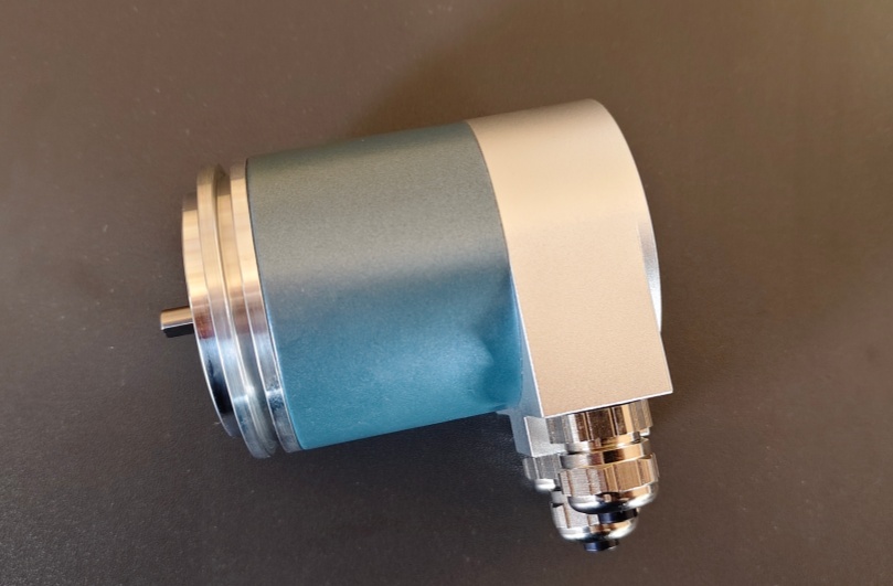
- aluminium housing with anodized finish
- 3 × PG9 radial connection layout
These are mechanical system components, not only encoder accessories.
System Limits
- Wrong Profibus termination → unstable RS485 communication
- Rope deviation or angular pull → unstable linear measurement
- Spring fatigue or oscillation → position repeatability degradation
This model uses PROFIBUS-DP with PNO Profile Class 2, not SSI, PROFINET, or analog output. The real system bottleneck is not encoder resolution but the combination of:
- rope mechanics
- spring return force
- RS485 signal integrity
- Profibus bus structure
The encoder itself provides:
- 4096 steps/rev
- 4096 revolutions
- programmable code
- 12 Mbaud communication
But even when the encoder electronics are operating normally, incorrect rope guidance or bus configuration will still produce unstable linear position data.
The Profibus documentation also explicitly states:
- S3/S4 termination must be ON when the encoder is the last bus station
- station address must be set between 3–99
- certified Profibus cable is recommended
These are system-critical conditions, not optional setup details.
Installation and Wiring Constraints
- Maintain straight rope travel and avoid lateral pull angle
- Protect the measuring cable from shock loading and sharp bending
- Keep measuring cable bending radius above R = 16 mm
- Do not exceed 8 m/s maximum control speed
- Configure Profibus termination correctly using S3/S4
- Use correct DataA / DataB / US / GND RS485 wiring
- Maintain shielding continuity through all PG cable entries
Failure boundary:
- Rope oscillation → unstable linear value
- Spring fatigue → repeatability drift
- Wrong Profibus termination → intermittent communication
- Address conflict → bus failure
- RS485 shielding fault → unstable telegram transmission
Replacement and Interface Mapping
- Suitable for Profibus linear displacement measurement systems
- Applicable where wire-draw measurement, 4096 × 4096 multiturn tracking, and RS485 Profibus communication are required
- Not suitable for simple rotary feedback or systems without controlled rope guidance
- Best used in applications with stable mechanical pull direction and properly designed Profibus topology
Key Data
- Model: CEW65M-01983
- Type: Wire draw absolute encoder
- Interface: PROFIBUS-DP
- Communication profile: PNO Profile Class 2
- Output level: RS485
- Singleturn resolution: 4096 steps
- Multiturn range: 4096 revolutions
- Code: Programmable
- Supply voltage: 11–27 VDC
- Protection: IP64
- Operating temperature: 0–60 °C
- Flange type: ZB50
- Shaft type: Ø6 mm round shaft / 18.3 mm
- Connector type: 3 × PG9
- Connector position: PG radial
- Measuring cable: Ø0.8 mm stainless steel cord
- Max control speed: 8 m/s
- Rope bending radius: R = 16 mm
- Options: 12 Mbaud / rope length transmitter / SL3020