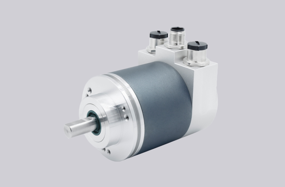
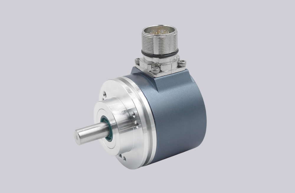
For SWF5B-FK-01, EncoderWorks can configure a custom compatible replacement solution when the installed system requires a 5 m draw-wire measuring range, bellows-protected cable entry, encoder-mounted drum conversion, 334 mm nominal drum scaling, cable exit alignment, and 70 m/s² acceleration margin to remain unchanged. The main failure boundary is a linear-position feedback system that may rotate the encoder shaft but still produce wrong travel values, cable wear, spring overload, drum tracking error, or unstable encoder feedback if the measuring range, cable path, drum scaling, encoder mounting interface, or cable-entry protection is changed. Typical production lead time: 15 working days.
This model belongs to the SWF cable-type displacement converter platform for use with absolute or incremental encoders. The 5 code identifies a 5 m measuring range, while B indicates the bellows option used as the standard cable-entry protection. The 01 suffix matches the documented basic-version concept, but the FK section is not shown in the standard order-code list from the supplied data, so it should be confirmed against the original nameplate, drawing, or machine record before production.
System Limits
The first limit is 5 m range scaling and drum-to-encoder conversion. Cable travel, nominal drum circumference, encoder resolution, controller scaling, and zero-position logic must match the installed system. If a 5 m version is replaced by a 10 m or longer range, or if the encoder conversion ratio is recalculated incorrectly, the machine may show proportional travel error even when the encoder signal appears stable.
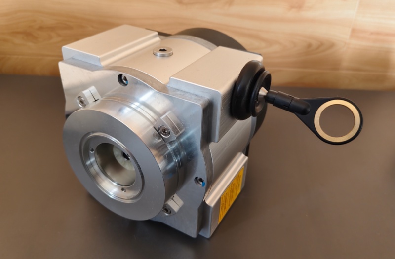
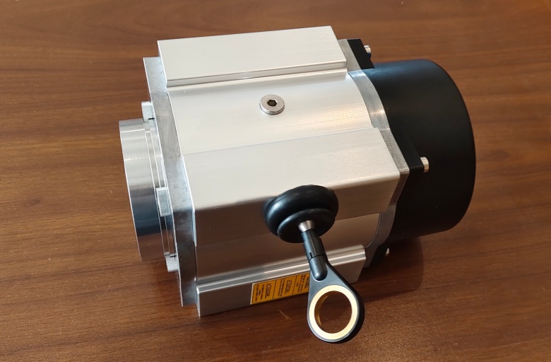
The second limit is cable path, bellows entry, and mechanical mounting. For a 5 m version, the cable speed and acceleration boundary must remain within 12 m/s and 70 m/s², and the cable should exit straight from the housing unless a suitable deflection accessory is engineered into the layout. Poor cable alignment, side pull, contaminated cable entry, wrong encoder mounting interface, or an unconfirmed FK mechanical variant can cause cable wear, spring stress, drum tracking error, water or dust ingress, and reduced service life.
Wiring & Installation
Before replacement, verify the measuring range, encoder type, encoder flange or adapter arrangement, cable exit position, bellows condition, cable routing, and the exact meaning of the FK section. The converter is normally supplied with or prepared for an encoder, so the mechanical converter and electrical encoder specification should be checked as one replacement boundary.
During installation, mount the housing rigidly to the stationary machine part and attach the cable eyelet to the moving part without twisting the cable. The cable exit should be downward or sideways where possible, and the cable must be pulled in a straight line relative to the housing. Keep the cable under tension, avoid snap-back, and do not exceed the travel, speed, or acceleration limits.
Custom Compatible Solution
EncoderWorks can configure the replacement around the installed SWF draw-wire interface:
- Match the 5 m measuring range, 334 mm nominal drum scaling, and encoder conversion ratio
- Preserve the B bellows cable-entry protection, cable exit orientation, and housing mounting geometry
- Confirm the FK section, encoder flange or adapter fit, cable path, and machine-side attachment method
- Review 12 m/s speed, 70 m/s² acceleration, draw force, IP cable-entry boundary, and drum tracking before shipment
Key Data
| Item | Data |
|---|---|
| Model | SWF5B-FK-01 |
| Device type | Cable-type displacement converter |
| Measuring range | 5 m |
| Conversion method | Linear cable travel to encoder shaft rotation |
| Drum circumference | 334 mm nominal |
| Accessory / cable entry | B, bellows standard |
| Intermediate code | FK requires confirmation |
| Version | 01 basic version / documented variant basis |
| Cable material | Stainless steel 1.4401 |
| Rope diameter | 1.3 mm standard, 0.8 mm optional |
| Cable draw force | 15 N max start, 30 N max end |
| Permissible cable speed | 12 m/s for 5 m range |
| Permissible cable acceleration | 70 m/s² for 5 m range |
| Approx. mass | 3 kg for 5 m range |
| Protection class | Housing IP65, cable entry IP54 |
| Key replacement checks | 5 m range, drum scaling, FK confirmation, cable exit alignment, bellows entry, encoder mounting, speed and acceleration limits |