We developed a custom solution for the BTF13-A1AM2020 wire draw encoder, intended for applications where long-stroke linear position must be measured reliably over 20 m while keeping installation structure simpler than rack, magnetostrictive, or long-scale systems. This configuration is built on the HighLine wire draw platform with an ATM60 SSI absolute encoder and MRA-F130 wire draw mechanism, so it is not just an encoder body. It is a complete linear measurement system where cable guidance, mounting geometry, stroke profile, and SSI integration determine whether the signal remains usable. Typical production lead time: 15 working days under confirmed configuration.
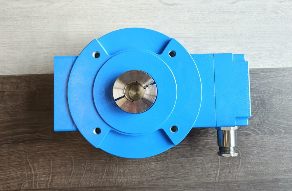
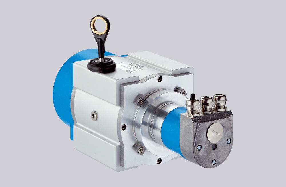
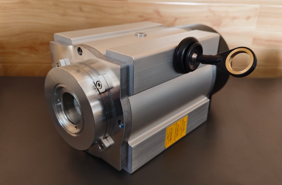
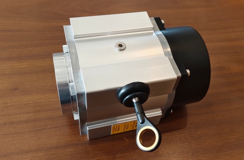
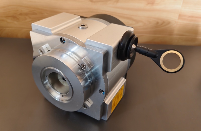
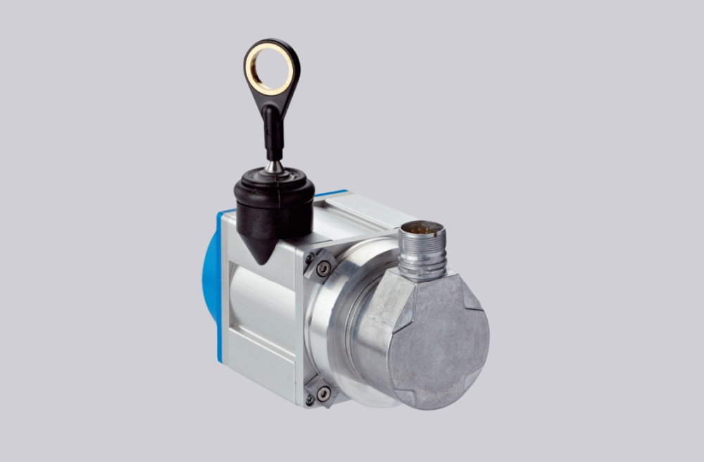
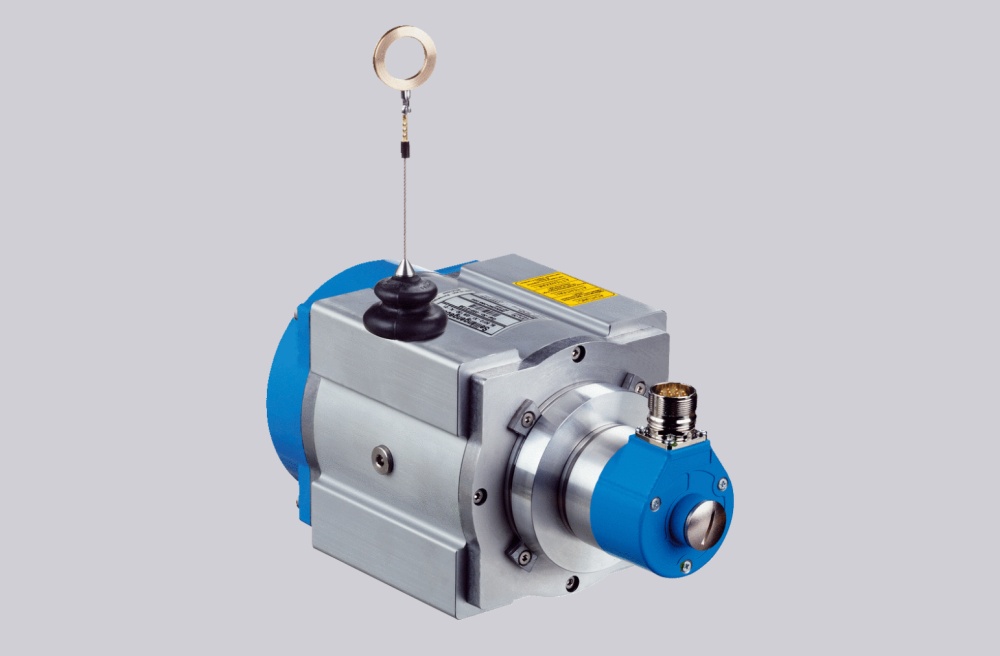
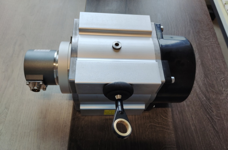
Custom Solution Photos
Stable measurement depends on wire alignment, mounting rigidity, return force behavior, and clean SSI signal integration.
System Limits
- Wire deflection or off-axis pulling → repeatability and service life drop quickly
- Resolution 0.05 mm does not mean sub-0.05 mm system accuracy
- Dynamic overload, shock pulling, or poor routing → wire mechanism life is reduced
This model is designed for 0 to 20 m measuring range, but the real engineering boundary is mechanical guidance, not encoder electronics. The combination resolution is 0.05 mm, while repeatability is ≤ 2 mm, linearity is ≤ ±2 mm, and hysteresis is ≤ 5 mm. That means this product is a long-stroke linear measurement system with mm-level system behavior, not a metrology-grade sub-millimeter precision stage.
The wire draw mechanism uses a 332.4 mm pull-out length per revolution, 10 to 20 N spring return force, 6 m/s operating speed, and 30 m/s² wire acceleration. The stated service life is typically 1,000,000 cycles, but the datasheet is clear that lifetime depends on application load, installation location, used measuring range, traversing speed, acceleration, and environmental conditions.
Installation and Wiring Constraints
- Keep the wire path as straight as possible
- Avoid side load, sharp deflection, and uncontrolled oscillation
- Use stable mounting points across the full stroke
- Do not treat the wire rope like a general-purpose pulling cable
- Match stroke length, speed, and acceleration to the mechanism limits
- Use the correct SSI wiring through the M23 12-pin radial connector
Signal logic:
- Data+ / Data- = SSI data
- Clock+ / Clock- = SSI clock
- SET = electronic zero set
- V/R = counting direction programming
Failure boundary:
- Poor wire guidance → linear error grows
- Side pull or misalignment → mechanism wear accelerates
- Over-aggressive motion profile → lifetime drops
- Wrong SSI integration or SET handling → position reference becomes invalid
This configuration works well only when the mechanical stroke path is controlled as carefully as the electrical interface.
Replacement and Interface Mapping
- Suitable for systems requiring 20 m long-stroke linear measurement
- Applicable where SSI absolute position output is preferred over analog displacement sensors
- Not suitable where the wire cannot run in a controlled straight path
- Optional accessories such as joint protection, brush attachment, deflection pulley, and flange adapter can be used to adapt the mechanism to the installation structure
Key Data
- Model: BTF13-A1AM2020
- Type: Wire draw encoder system
- Measuring range: 0 to 20 m
- Interface: SSI
- Resolution: 0.05 mm
- Repeatability: ≤ 2 mm
- Linearity: ≤ ±2 mm
- Hysteresis: ≤ 5 mm
- Supply voltage: 10 to 32 V
- Power consumption: ≤ 0.8 W
- Wire material: stainless steel V4A
- Wire diameter: 0.81 mm
- Return force: 10 to 20 N
- Pull-out length per revolution: 332.4 mm
- Operating speed: 6 m/s
- Wire acceleration: 30 m/s²
- Service life: typ. 1,000,000 cycles
- Enclosure rating: IP64
- Operating temperature: -20 to +70 °C
- Weight: 5.5 kg