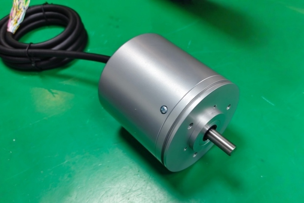
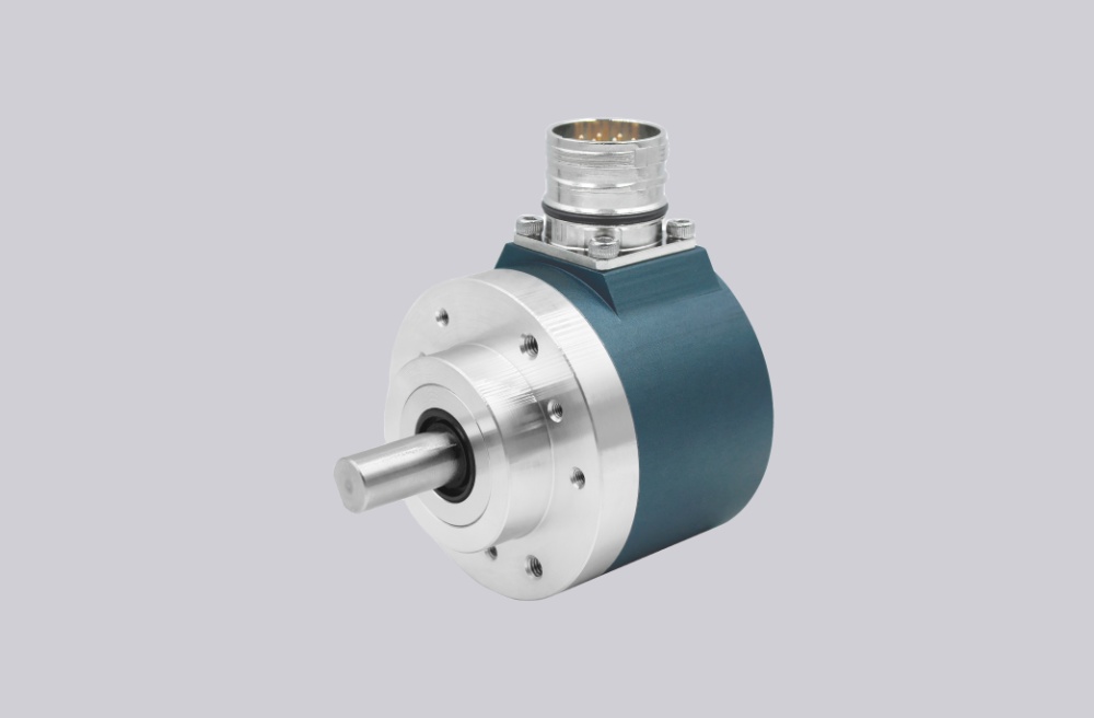
EncoderWorks configures AVS78E-022K2A0GN-0012 as a custom compatible replacement solution for explosion-proof SSI singleturn feedback where RS422 clock/data timing, 12-bit Gray code interpretation, K2 axial cable mapping, preset input, counting-direction input, and Ø12 mm servo-flange alignment must remain matched to the installed controller. The failure boundary is not only the 10–30 VDC supply, but also Pulse ± polarity, Data ± polarity, monoflop timing, clock pause, controller sampling edge, rear cable clearance, shield continuity, and explosion-proof certificate scope. Typical production lead time: 15 working days.
This model is used where the controller reads a 12-bit absolute singleturn position word through an SSI interface from a solid-shaft encoder with a servo flange and axial cable exit. A compatible replacement must preserve the Gray output code, SSI clock response, RS422 differential wiring, zero-set behavior, direction input logic, K2 2 m cable execution, Ø12 mm shaft interface, and hazardous-area installation boundary.
System Limits
The first system boundary is the SSI data timing and Gray-code word structure. AVS78E-022K2A0GN-0012 must return the same 12-bit position value when the controller sends its clock sequence. If the replacement is supplied with Binary code, a different bit length, incorrect MSB / LSB handling, wrong sampling edge, insufficient clock pause, or mismatched monoflop behavior, the RS422 signals may still look clean while the controller calculates the wrong angle. Typical failures include a fixed position offset, one-bit shift, unstable zero position, reversed direction, or incorrect value after preset.
The second boundary is the K2 axial cable and servo-flange mechanical alignment. Pulse + / Pulse -, Data + / Data -, GND, supply, preset, counting direction, shield path, cable bend radius, and rear exit clearance must match the installed wiring. A correct SSI encoder can still fail if the clock pair is reversed, the data pair is reversed, the preset line is triggered unintentionally, the direction input is held in the wrong state, or the 2 m axial cable is sharply bent behind the encoder. Mechanically, the Ø12 mm × 25 mm solid shaft, servo flange, coupling centering, axial load, radial load, and aluminum housing fit must be checked together.
Wiring & Installation
Before replacement, confirm the full installed model code, SSI bit length, Gray code requirement, controller clock frequency, monoflop timing, clock pause, Pulse ± mapping, Data ± mapping, preset input use, counting-direction input state, K2 cable length, axial exit direction, servo-flange geometry, and Ø12 mm shaft interface. This SSI version should not be inferred from PROFIBUS, clamping-flange, K5, KR, or other interface variants because the controller depends on clock/data timing rather than fieldbus addressing or network parameterization.
During installation, verify supply wiring, GND, differential clock pair, differential data pair, preset line, and counting-direction line before powering the system. Keep the SSI cable away from motor and drive wiring, maintain low-impedance shield continuity, and avoid cable kinking, tensile load, or shearing load at the axial exit. The servo flange should seat concentrically, and the coupling should not force the Ø12 mm shaft off center. Explosion-proof suitability must be confirmed against the installed hazardous-area requirement and certificate scope before shipment.
Custom Compatible Solution
- Match SSI RS422 behavior, 12-bit singleturn feedback, Gray output code, monoflop timing, and controller clock expectation
- Preserve Pulse ±, Data ±, supply, GND, preset input, counting-direction input, shield continuity, and axial cable clearance
- Adapt the Ø12 mm × 25 mm solid shaft, servo flange, K2 9-strand 2 m axial cable, aluminum housing, and IP66 sealing boundary
- Review clock frequency, line length, sampling edge, servo-flange alignment, coupling load, hazardous-area certificate scope, and commissioning requirements before shipment
Key Data
| Item | Data |
|---|---|
| Model | AVS78E-022K2A0GN-0012 |
| Encoder type | Explosion-proof singleturn absolute rotary encoder |
| Interface | SSI |
| Electrical standard | RS422 |
| Supply voltage | 10–30 VDC |
| Output code | Gray |
| Singleturn resolution | 12 bit |
| Multiturn resolution | Not applicable |
| Total position structure | 12-bit absolute singleturn data |
| SSI timing boundary | Monoflop time and clock pause require controller-side confirmation |
| Connection | K2, 9-strand cable, 2 m |
| Cable exit | A, axial |
| Control inputs | Zero-set / preset and counting direction |
| Shaft / flange | Ø12 mm × 25 mm solid shaft, servo flange |
| Housing material | N, aluminum |
| Protection class | IP66 sealing boundary requires confirmation against installed version |
| Hazardous-area boundary | ATEX / IECEx explosion-proof compliance requires confirmation against installed certificate scope |
| Key replacement checks | SSI clock frequency, Pulse ±, Data ±, Gray code, 12-bit word length, preset, direction input, shield continuity, K2 axial cable, Ø12 mm servo-flange alignment |