We configured a custom solution for the PMG10-SHD.13P0.30000.A encoder, intended for applications where absolute position data must be integrated into a Profibus DP control network with stable device addressing and predictable parameter behavior. This configuration is built on the PMG10 solid shaft platform with Ø11 mm shaft, EURO flange B10, protection class D, and Profibus-DPV0 interface, making it suitable for dusty or abrasive industrial environments where bus-side integration is more critical than simple standalone sensing. It is not a basic position transmitter. It is a network-oriented absolute feedback device where bus addressing, termination logic, and controller-side parameter mapping determine whether the position value remains usable. Typical production lead time: 15 working days under confirmed configuration.
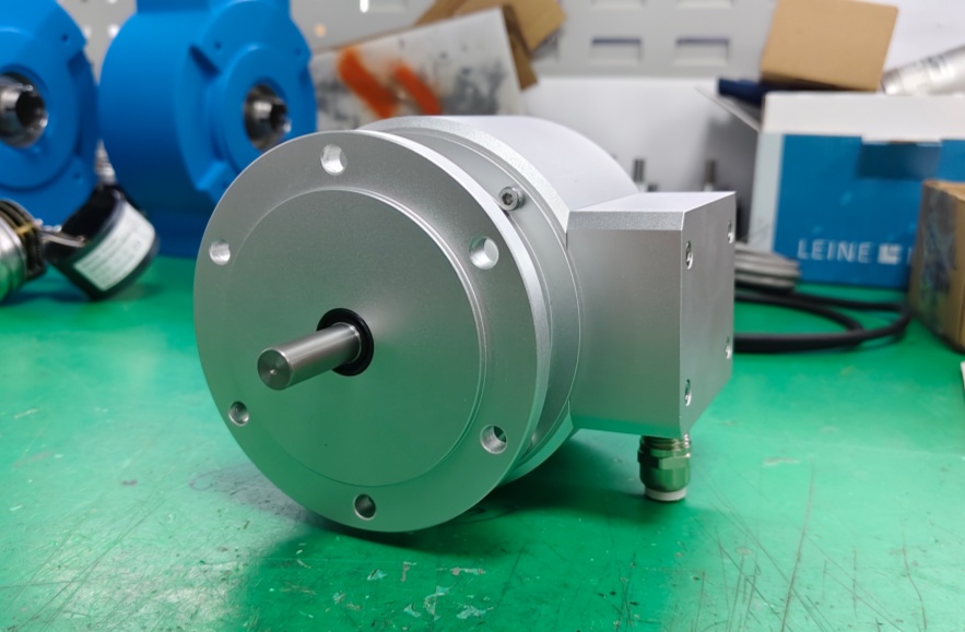
Custom Solution Photos
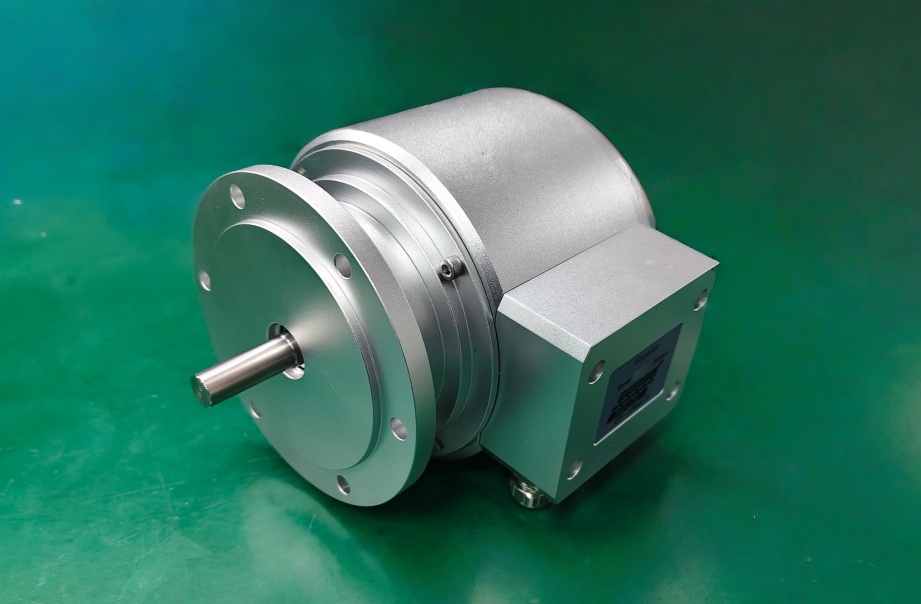
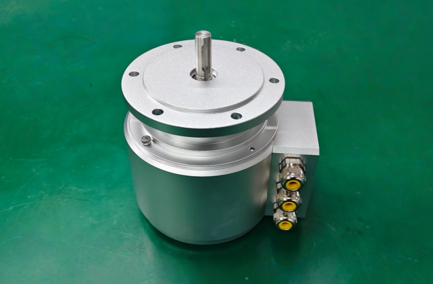
Stable operation depends on shaft alignment, bus connecting box integrity, address setting accuracy, and correct Profibus wiring.
System Limits
- Wrong Profibus address setting → device cannot be integrated correctly into the network
- Incorrect terminating resistor state → bus communication becomes unstable
- Wrong preset, scaling, or rotating direction parameters → system position logic becomes invalid
This model uses Profibus-DPV0 with 13 bit singleturn resolution and no multiturn output in this coded version. The main limit is not the magnetic sensing body itself. It is bus-side configuration discipline. The PMG10 platform supports programmable parameters for steps per revolution, number of revolutions, preset, scaling, and rotating direction, so system failure is more likely to come from wrong network integration or parameter mapping than from the encoder structure. The device address is defined by rotary switches in the bus connecting box, and the terminating resistor must be set correctly depending on whether the encoder is the last user on the segment.
Installation and Wiring Constraints
- Supply voltage must remain within 10 to 30 VDC
- Profibus terminals A / B / UB / GND must be wired correctly
- Set the rotary-switch address before commissioning
- Set terminating resistor ON only for the last user, otherwise OFF
- Keep bus wiring separate from strong noise sources
- Use programmed preset, scaling, and rotating direction only when the control logic is clearly defined
Integration logic:
- A = negative serial data transmission
- B = positive serial data transmission
- UB / GND = bus power supply
- Factory setting of user address = 00
- Diagnostic support includes position or parameter error
Incorrect addressing, termination, or parameter mapping will invalidate position data before any mechanical limit is reached.
Replacement and Interface Mapping
- Suitable for systems requiring Profibus DP absolute position feedback
- Applicable where bus address control and parameter integration are critical
- Not suitable where the controller cannot manage Profibus addressing, preset, or scaling logic
- This version is focused on networked absolute feedback, not SSI-based integration or optional incremental supplement outputs
Key Data
- Model: PMG10-SHD.13P0.30000.A
- Type: Absolute encoder, Profibus DP
- Shaft: Ø11 mm solid shaft
- Mounting: EURO flange B10
- Protection class: D, optimized for dusty abrasive environment
- Supply voltage: 10 to 30 VDC
- Interface: Profibus-DPV0
- Transmission rate: 9.6 to 12000 kBaud
- Singleturn resolution: 13 bit / 8192 steps
- Multiturn resolution: none in this coded version
- Initializing time: ≤500 ms
- Max operating speed: ≤6000 rpm
- Admitted shaft load: ≤450 N axial, ≤650 N radial
- Protection: IP66 / IP67
- Operating temperature: -40 to +85 °C
- Connection: Bus connecting box
PMG10-SHL.15P0.36000.A Incremental Encoder
PMG10-SHD.1FP0.36000.A High Resolution Encoder
PMG10-SHD.13P0.36000.A Incremental Encoder Solution
PMG10-SHD.15P0.36000.A Industrial Encoder