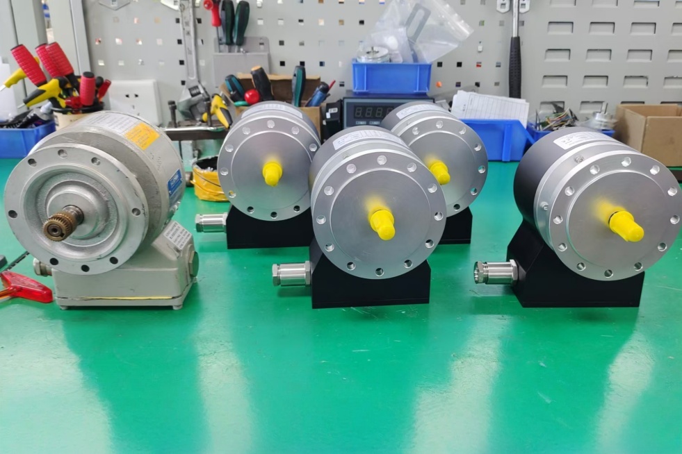
EncoderWorks develops custom compatible replacement solutions for 67-11616-1024 and 67-11617-1024 within the SERIE 67 incremental encoder platform, where 1024 PPR resolution, A/B/C channel logic, complementary inverted signals, RS422 / Push-Pull output variants, Ø10 mm solid-shaft interface, IP66 sealing, and 58 mm compact industrial housing must remain fully matched to the installed motion control system. The failure boundary is not limited to electrical compatibility, but also includes signal timing deviation, incorrect wiring configuration, reference pulse mismatch, shield grounding instability, mechanical coupling misalignment, and enclosure constraint errors. Typical production lead time: 15 working days.
Both 67-11616-1024 and 67-11617-1024 operate on the same SERIE 67 mechanical and electrical platform. The difference between the two models is defined by internal configuration code, typically affecting output assignment, signal mapping, or connection variant, while maintaining identical resolution, shaft interface, and core encoder architecture. A compatible replacement must preserve 1024 pulses per revolution, 90° quadrature relationship between A and B channels, C reference pulse behavior, output driver compatibility (RS422 or Push-Pull depending on configuration), and the same IP66 and 58 mm housing boundary.
System Limits
The first system boundary is signal integrity and counter interface behavior. Both models must be evaluated against the controller’s maximum input frequency (up to 300 kHz), edge detection capability, A/B phase interpretation logic, and C channel reference usage. Incorrect mapping of A/B channels, missing inverted signals, or incorrect output driver type can result in valid motion detection but incorrect speed scaling, direction reversal, or unstable reference positioning. Cable length, shielding quality, and EMI exposure from drives or braking circuits directly influence counting stability in high-speed applications.
The second boundary is mechanical integration and housing constraint. SERIE 67 uses a compact 58 mm housing with Ø10 mm solid shaft, designed for flexible flange anti-rotation mounting. Misalignment of the shaft coupling, excessive radial load, or incorrect flange fixation can introduce phase jitter, bearing stress, or premature wear. The IP66 sealing structure must be maintained under vibration, humidity, and industrial contamination conditions. Connector alignment and cable routing clearance must be verified before installation, especially in confined mounting spaces.
Configuration Logic (Model Differentiation)
The distinction between 67-11616-1024 and 67-11617-1024 is defined by configuration-level encoding rather than mechanical structure. Both models share identical resolution, housing geometry, shaft interface, and environmental rating. The difference lies in output configuration and internal signal assignment, which must be confirmed against the original system wiring diagram before replacement.
Incorrect substitution between these two configuration variants may result in:
- A/B channel inversion or misinterpretation
- Missing or incorrectly mapped C reference pulse
- Connector pin mismatch in system integration
- Inconsistent direction logic at controller level
For this reason, configuration verification is mandatory even when mechanical compatibility appears identical.
Wiring & Installation
Before replacement, confirm full system parameters including 1024 PPR resolution, A/B/C signal structure, inverted channel requirement, output type (RS422 or Push-Pull), supply voltage range, connector pin assignment, cable shielding method, shaft diameter (Ø10 mm), coupling type, housing size (58 mm), and available installation clearance. Both 11616 and 11617 variants must be treated as configuration-sensitive models rather than interchangeable mechanical units.
During installation, verify correct connector mapping before power-up. Ensure shield termination is grounded at a single reference point to avoid ground loop interference. The shaft coupling must be aligned concentrically without axial preload or radial stress. Improper installation may lead to phase jitter, intermittent count loss, or unstable reference pulse detection at higher operating speeds.
Custom Compatible Solution
- Match 1024 PPR incremental encoding with A/B quadrature and C reference pulse behavior
- Preserve RS422 / Push-Pull output compatibility with correct inverted signal assignment
- Maintain 58 mm compact housing envelope and Ø10 mm solid shaft interface
- Ensure correct configuration mapping between 67-11616-1024 and 67-11617-1024
- Validate EMI resistance, shielding integrity, and counter frequency margin up to 300 kHz
Key Data
| Item | Data |
|---|---|
| Models | 67-11616-1024 / 67-11617-1024 |
| Encoder type | Incremental solid-shaft encoder |
| Resolution | 1024 PPR |
| Signal channels | A, B, C with complementary inverted signals |
| Signal format | Quadrature + reference pulse |
| Output type | RS422 / Push-Pull (configuration dependent) |
| Phase shift | 90° nominal |
| Max output frequency | Up to 300 kHz |
| Shaft type | Solid shaft |
| Shaft diameter | Ø10 mm |
| Housing size | 58 mm compact industrial housing |
| Protection rating | IP66 |
| Max speed | 6000 rpm application dependent |
| Mounting | Flexible flange anti-rotation system |
| Configuration difference | Output mapping / wiring assignment (11616 vs 11617) |
| Key replacement checks | PPR, output type, channel mapping, inverted signals, connector pinout, shielding, mechanical alignment, configuration code |