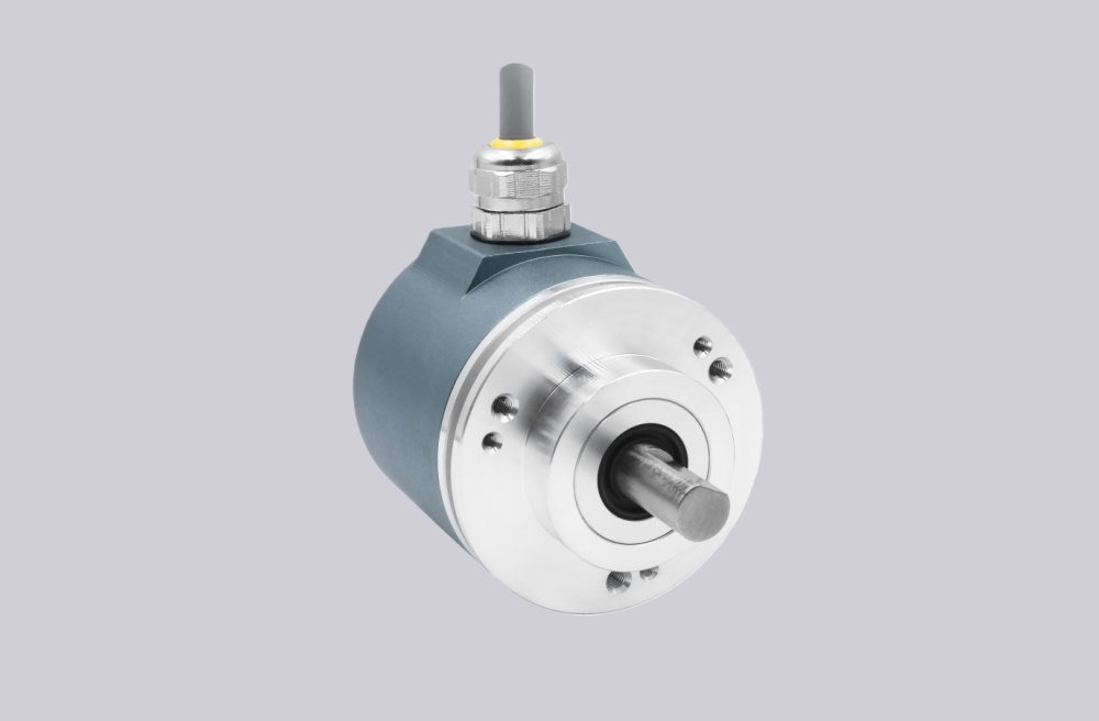
We configured a custom solution for the PMG10-SHD.15P0.36000.A encoder, intended for applications where absolute position feedback must be monitored and diagnosed reliably over Profibus DP with clear system status visibility. This configuration is based on the PMG10 solid shaft platform with Ø11 mm shaft, EURO flange B10, protection class D, using Profibus-DPV0/V2 communication with diagnostic capability, 13 bit singleturn, and 16 bit multiturn structure. It is not a basic encoder for position output only. It is a diagnostic-oriented feedback device where system status, parameter validation, and bus communication integrity determine whether position data remains trustworthy. Typical production lead time: 15 working days under confirmed configuration.
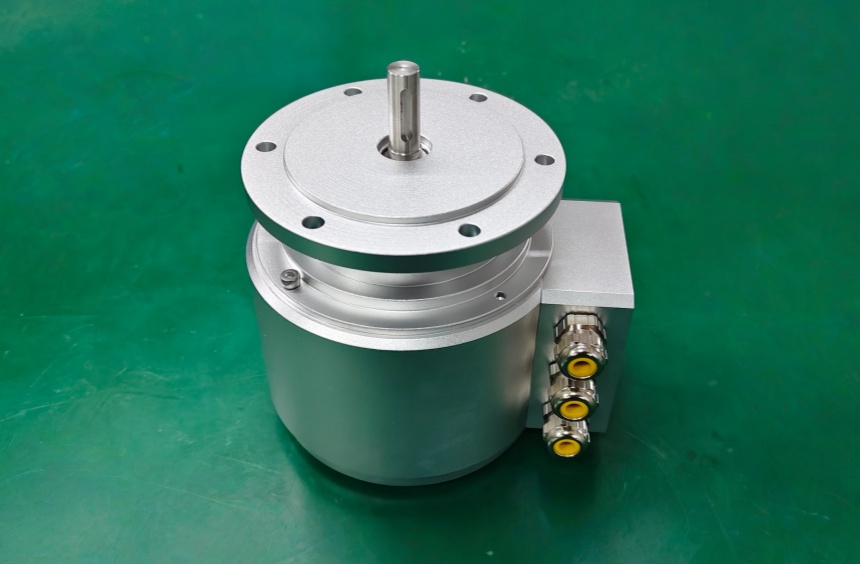
Custom Solution Photos
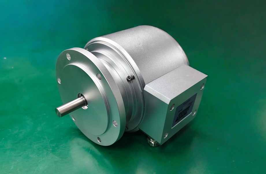
Reliable operation depends on shaft alignment, bus connection integrity, LED status visibility, and correct Profibus configuration.
System Limits
- Bus communication error or address conflict → diagnostic data cannot be read correctly
- Parameter mismatch → system reports position or parameter error
- Controller cannot interpret diagnostic signals → system fault remains undetected
This model supports Profibus diagnostic functions, including detection of position errors and parameter errors, and provides status indication via DUO-LEDs and additional LEDs on the device. However, diagnostics are only effective when the controller is correctly configured to read and interpret them. The system limit is not the sensing element, but the diagnostic integration path.
Installation and Wiring Constraints
- Supply voltage: 10 to 30 VDC
- Set Profibus address using rotary switches before commissioning
- Configure terminating resistor correctly depending on bus topology
- Ensure diagnostic signals are mapped in the controller
- Keep bus wiring stable and isolated from noise sources
- Use preset and scaling only within defined logic
Integration logic:
- A / B = Profibus communication lines
- UB / GND = power supply
- Diagnostic output includes position error and parameter error signals
- Device status visible via LED indicators in bus connecting box and rear side
Failure boundary:
- Diagnostics not integrated → faults cannot be detected
- Wrong address or termination → communication instability
- Incorrect parameter setup → persistent error states
System reliability depends on diagnostic integration, not just encoder output.
Replacement and Interface Mapping
- Suitable for systems requiring Profibus encoder with diagnostic capability
- Applicable where system status monitoring and fault detection are critical
- Not suitable where controller cannot process diagnostic information
- Designed for networked control systems, not standalone sensing
Key Data
- Model: PMG10-SHD.15P0.36000.A
- Type: Absolute encoder, Profibus DP
- Shaft: Ø11 mm solid shaft
- Mounting: EURO flange B10
- Protection class: D, for dusty abrasive environments
- Supply voltage: 10 to 30 VDC
- Interface: Profibus-DPV0/V2
- Transmission rate: 9.6 to 12000 kBaud
- Singleturn resolution: 13 bit
- Multiturn resolution: 16 bit
- Initializing time: ≤500 ms
- Max speed: ≤6000 rpm
- Admitted shaft load: ≤450 N axial, ≤650 N radial
- Protection: IP66 / IP67
- Operating temperature: -40 to +85 °C
- Connection: Bus connecting box
PMG10-SHD.13P0.30000.A Incremental Encoder
PMG10-SHL.15P0.36000.A Encoder Solution
PMG10-SHD.1FP0.36000.A Incremental Encoder
PMG10-SHD.13P0.36000.A High Resolution Encoder