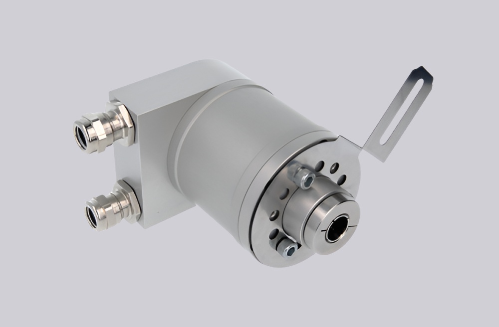
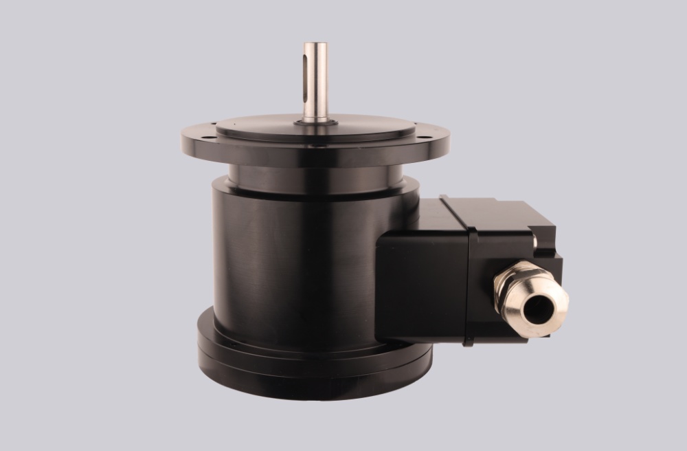
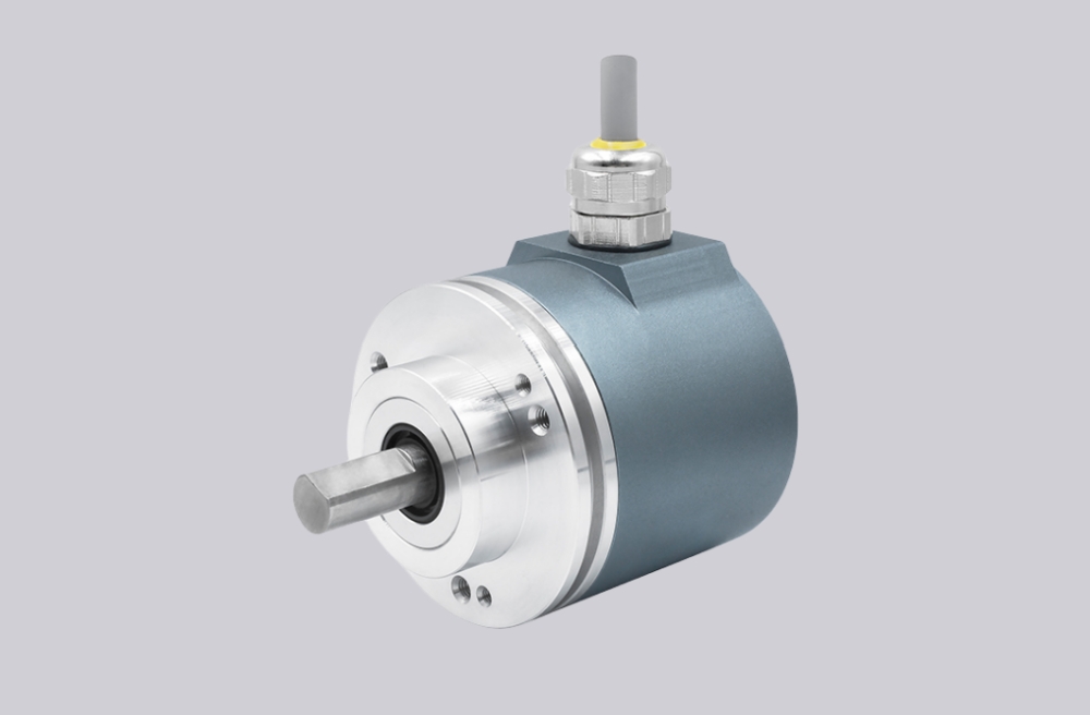
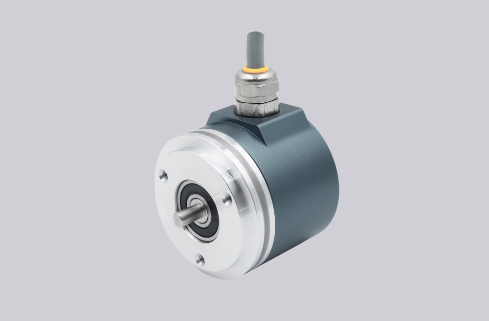
We developed a custom solution for the UCE-AV002-0013-F10W-2RW encoder, intended for hazardous-area systems where 0–10 V analog position feedback must remain stable under vibration, moisture, and industrial noise while meeting Zone 1 and 21 oil-and-gas installation requirements. This configuration uses a solid Ø10 mm shaft, Ø78 mm ATEX clamp flange, stainless steel V4A housing, magnetic sensing, and a voltage analog interface. It is not a fieldbus encoder. It is an analog absolute feedback solution where scaling, load resistance, signal routing, and hazardous-area installation quality determine whether the output remains usable. Typical production lead time: 15 working days.
Custom Solution Photos
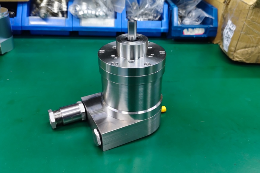
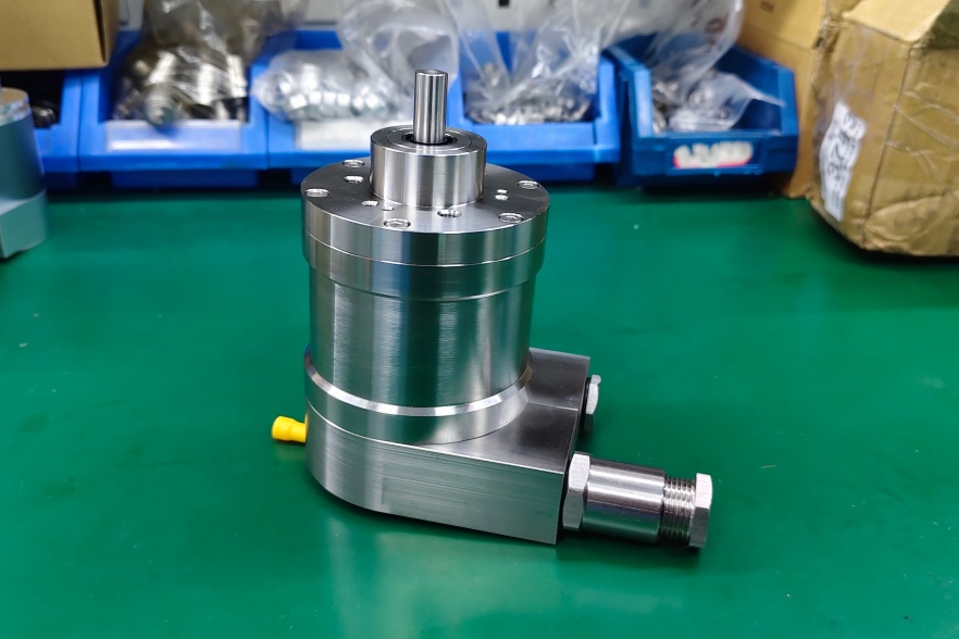
Stable operation depends on clamp mounting quality, radial cable/connector routing, stainless enclosure integrity, and correct analog signal scaling.
System Limits
- Load resistance below 5 kΩ → analog output accuracy may degrade
- Wrong Set1 / Set2 configuration → measuring range or zero point becomes incorrect
- Noise on analog output line → unstable voltage feedback at PLC input
This model uses 0–10 V analog voltage output, not SSI, Profibus, PROFINET, or bit-parallel logic. The main system bottleneck is therefore analog signal quality and range setting. It provides 13-bit singleturn sensing, 0-bit multiturn, and supports setting the start and end positions through cable or connector. The minimum measuring range is 0–11.25°, and output resolution can reach up to 13 bit over the full range, but when the measuring range is below 90°, usable resolution is reduced.
Installation and Wiring Constraints
- Wire Power Supply / GND / Analog Output / Set1-Direction / Set2-Zero Set / Shielding correctly
- Keep minimum load resistance at ≥5 kΩ
- Use shielding carefully because analog voltage is sensitive to EMC noise
- Respect cable bend radius: 50 mm fixed / 100 mm flexing
- Maintain sealing for CE + ATEX Zone 1 & 21 Oil+Gas service
- Do not exceed 60 N axial / 80 N radial shaft load
Failure boundary:
- Wrong range setting → incorrect 0–10 V scaling
- Poor shielding → noisy analog feedback
- Excess shaft load → reduced mechanical reliability
- Poor hazardous-area sealing → installation risk
Replacement and Interface Mapping
- Suitable for analog voltage absolute position feedback systems
- Applicable where 0–10 V output, ATEX Zone 1 / 21 approval, and stainless housing are required
- Not suitable where digital fieldbus, SSI, or parallel output is expected
- Best used where PLC analog input quality, shielding, and range setup can be controlled
Key Data
- Model: UCE-AV002-0013-F10W-2RW
- Type: Absolute encoder, analog voltage
- Interface: 0–10 V analog voltage
- Sensor technology: Magnetic
- Singleturn resolution: 13 bit
- Multiturn: 0 bit / singleturn
- Supply voltage: 8–32 VDC
- Typical current: 15 mA @ 24 V no load
- Start-up time: <500 ms
- Linearity: 0.15%
- Settling time: 32 ms
- Flange: Clamp flange, Ø78 mm ATEX
- Shaft: Solid Ø10 mm, single flat, length 20 mm
- Housing: Stainless steel V4A / 316L
- Shaft load: 60 N axial / 80 N radial
- Max speed: ≤3000 rpm
- Protection: IP66 / IP67
- Temperature: -30 °C fixed, -5 °C flexing, up to +70 °C
- Approval: CE + ATEX Zone 1 & 21 Oil+Gas