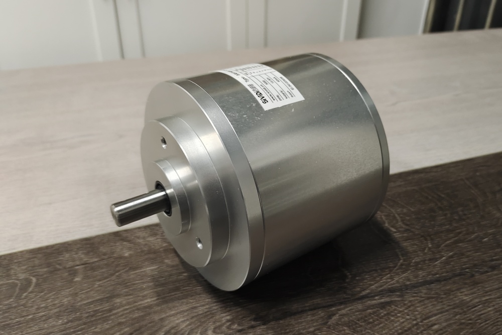
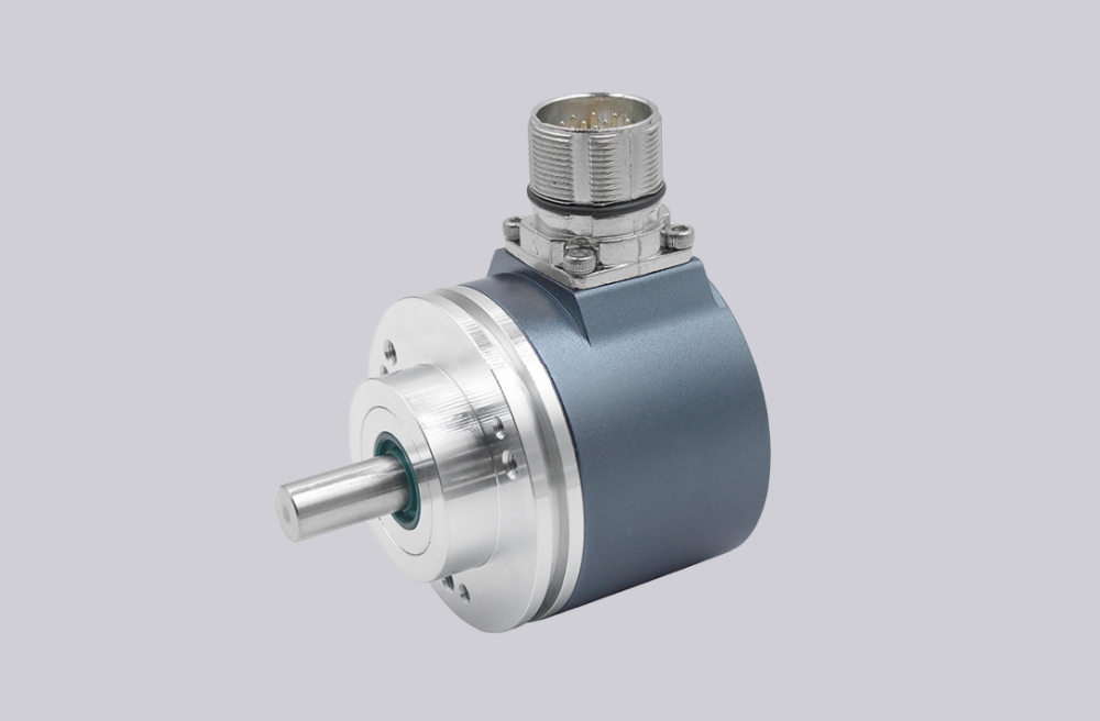
EncoderWorks can configure RVI70E-011KAR61N-01000 as a custom compatible replacement solution for explosion-proof incremental feedback where 1000 PPR, 10–30 V push-pull output, and a 10 m radial cable path must remain stable with the installed controller. The failure boundary is defined by A/B/Z complementary mapping, counter scaling, long-cable noise exposure, Ø10 mm clamping-flange fit, PE continuity, and hazardous-area sealing. Typical production lead time: 15 working days.
This model is used where incremental speed or position feedback must be transmitted through a longer field cable in a protected industrial installation. A compatible replacement must preserve the controller’s 1000 PPR scaling, push-pull input behavior, radial cable route, aluminium housing envelope, and explosion-proof mounting boundary.
System Limits
The first system boundary is the 1000 PPR push-pull signal relationship over a 10 m cable. RVI70E-011KAR61N-01000 uses A/B/Z feedback with complementary channels and a 10–30 V push-pull output circuit, so the controller must receive the same pulse count, channel polarity, Z reference behavior, and direction logic. If the replacement is configured with another PPR, missing complementary channels, wrong voltage level, inverted A/B order, or poor edge quality over the long cable, the machine can fail with wrong speed feedback, missed counts, direction reversal, reference loss, or unstable counting. The 200 kHz output boundary should still be checked against maximum shaft speed and controller counter margin.
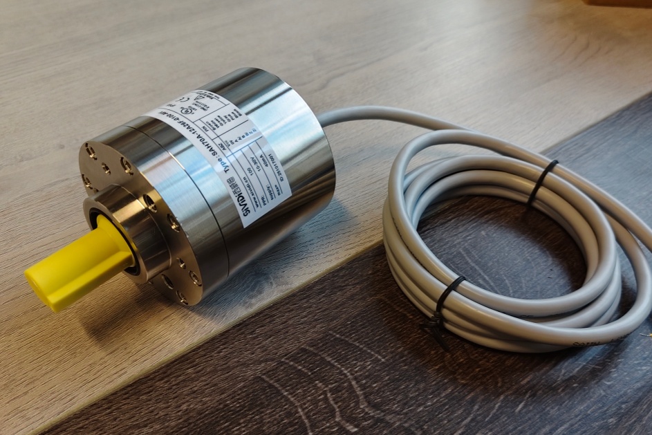
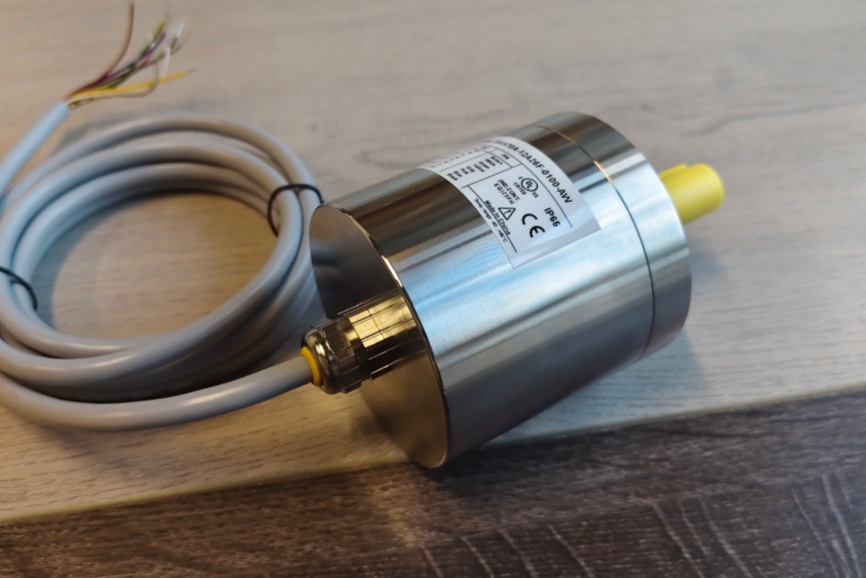
The second boundary is the Ø10 mm clamping-flange installation with radial 10 m cable routing. This version uses an aluminium housing, Ø10 mm × 20 mm shaft, and radial cable exit, so shaft fit, flange face, cable bend radius, gland stress, PE continuity, shielding, sealing exposure, and bearing load must be controlled together. Excessive radial load, flange misalignment, cable pulling force, poor grounding, or damaged sealing can cause bearing stress, signal dropout, water or dust ingress, and early mechanical failure. Explosion-proof suitability must be confirmed against the installed hazardous-area requirement and certificate scope before shipment.
Wiring & Installation
Before replacement, confirm the full installed model code, 1000 PPR requirement, 10–30 V supply, push-pull controller input, A/B/Z and complementary channel mapping, 10 m radial cable route, PE connection, shaft/flange dimensions, and hazardous-area requirement. The cable path should be reviewed carefully because long push-pull wiring can become unstable when routed near motor, brake, or inverter power cables.
During installation, the Ø10 mm clamping flange should sit flat and the coupling should not force the shaft off center. Keep the radial cable exit free from sharp bends, vibration load, or gland tension, and maintain PE and shield continuity back to the cabinet. After mounting, verify direction, Z reference behavior, and count stability at low and operating speed before returning the machine to normal operation.
Custom Compatible Solution
- Match 1000 PPR, 10–30 V push-pull output, A/B/Z channels, and complementary signal mapping
- Preserve counter scaling, edge timing, Z reference behavior, direction logic, and controller input compatibility
- Adapt the Ø10 mm shaft, clamping flange, 10 m radial cable, aluminium housing, and sealing boundary
- Review PE continuity, long-cable routing, shaft load, IP exposure, and hazardous-area requirement before shipment
Key Data
| Item | Data |
|---|---|
| Model | RVI70E-011KAR61N-01000 |
| Encoder type | Explosion-proof incremental rotary encoder |
| Pulse count | 1000 PPR |
| Output circuit | 1, 10–30 V push-pull |
| Signal channels | A, B, Z and complementary channels |
| Supply voltage | 10–30 V DC |
| Output frequency | Max. 200 kHz class boundary |
| Connection | KA, 10 m cable |
| Cable exit | R, radial |
| Shaft / flange | 011, Ø10 mm × 20 mm shaft with clamping flange |
| Housing material | N, aluminium |
| Protection class | IP66 / IP67 sealing boundary requires confirmation against installed version |
| Hazardous-area boundary | Explosion-proof compliance requires confirmation against installed certificate scope |
| Key replacement checks | 1000 PPR scaling, push-pull input match, A/B/Z mapping, 10 m radial cable route, PE continuity, Ø10 mm shaft fit, sealing boundary |
Related Models
RVI70E-011KAR61N-01024 Incremental Encoder
RVI70E-011KAR61I-05000 Incremental Encoder Solution
RVI70E-011K5R61I-01024 Industrial Encoder
RVI70E-011K2A61N-01024 Encoder Solution
RVI70E-021K2A6XN-01024 Incremental Encoder