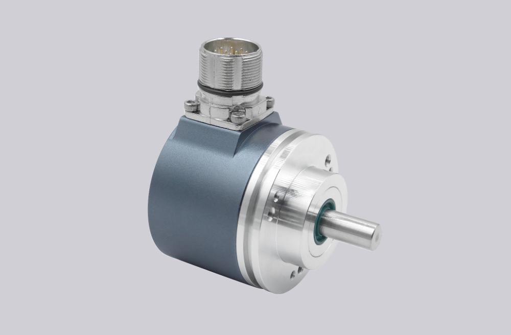
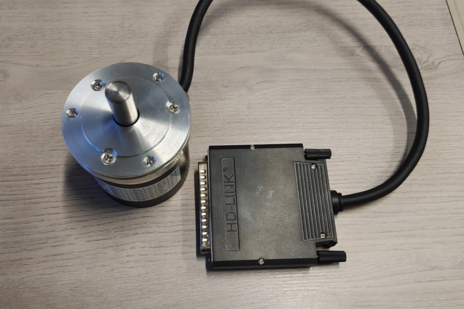
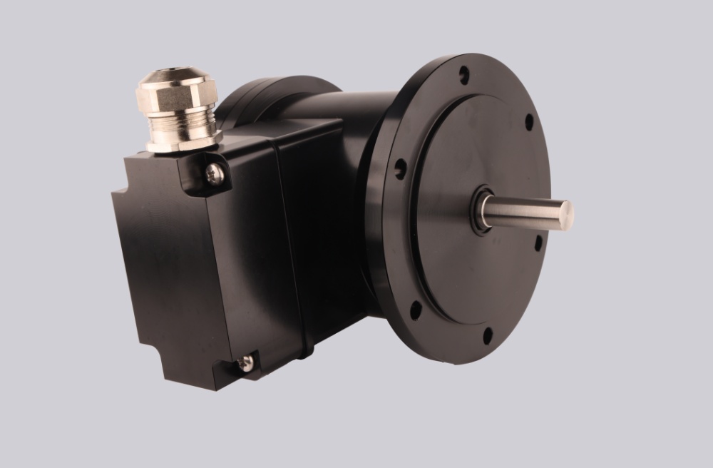
We developed a custom solution for the POG10 D 500 I + FSL encoder, intended for heavy-duty drive systems where 500 PPR HTL feedback and mechanical speed switching must remain stable under vibration, terminal-box wiring, high temperature, and EMC noise. This is a D-output POG10 configuration with FSL, so it provides K1 / K2 incremental feedback plus a centrifugal force switch, not K0 index feedback.
Typical production lead time: 15 working days.
Model reading is direct:
- D = K1, K2 output signals
- 500 = 500 pulses per revolution
- I = 9–30 VDC, HTL output with inverted signals
- + FSL = centrifugal force switch
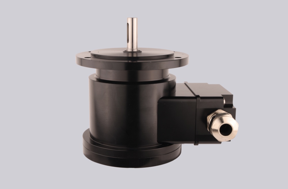
- POG10 = Ø11 mm shaft, EURO flange B10, terminal-box heavy-duty encoder body
At 500 PPR, counter overload is not normally the first weak point. The feedback side usually fails at terminal grounding, shielding continuity, coupling torsion, or K1/K2 phase stability. The FSL side fails for a different reason: wrong switching speed selection.
Where the System Fails First
The encoder output supports ≤120 kHz, but at 500 PPR the system usually has enough counter margin. Most real problems come from poor grounding, loose terminal wiring, or shield breaks near the terminal box. The signal may still be present, but edge timing becomes untrustworthy.
For the FSL section, the switching speed is not a field-adjustable detail. It must be specified when ordering and is permanently defined at the factory. If the selected switching speed does not match the drive protection requirement, the switch can trip too early, trip too late, or fail to protect the machine at the intended point.
Typical failure points:
- Wrong FSL switching speed → protection value is meaningless
- Poor terminal grounding → false HTL edges
- Shield interruption → unstable speed feedback
- Rigid coupling → torsional shock into the Ø11 mm shaft
- Mechanical vibration → unstable switch behavior
- Wrong K1/K2 phase reading → reversed direction
Because this is a D version, do not add K0 reference logic. Use a separate home signal if index referencing is required.
Mechanical and Switch Boundary
The POG10 + FSL version has different limits from the standard POG10. With FSL, vibration resistance is 10 g, shock resistance is 100 g / 6 ms, rotor inertia is 220 gcm², and weight is about 2.3 kg. The allowable operating speed is linked to the selected switching speed: n ≤ 1.25 × ns.
The FSL switching range is 850–4900 rpm. Its contact capacity is 0.05–6 A / 230 VAC or 0.05–1 A / 125 VDC. Treat it as a mechanical protection element, not as another encoder output.
Installation Notes
- Keep the model format as POG10 D 500 I + FSL
- Do not add K0 logic; D = K1 / K2 only
- Specify the correct FSL switching speed before production
- Keep terminal-box grounding continuous
- Separate encoder wiring from inverter and motor power cables
- Test both HTL feedback and FSL switch contacts during commissioning
- Use a flexible coupling suitable for Ø11 mm shaft
- Check shielding and grounding before replacing the encoder
Key Data
- Model: POG10 D 500 I + FSL
- Type: Heavy-duty incremental encoder with centrifugal switch
- Resolution: 500 PPR
- Output: HTL with inverted signals
- Signals: K1, K2 + inverted
- Supply voltage: 9–30 VDC
- Output frequency: ≤120 kHz
- FSL switching range: 850–4900 rpm
- FSL switching capacity: 0.05–6 A / 230 VAC; 0.05–1 A / 125 VDC
- Shaft: Ø11 mm stainless steel
- Flange: EURO flange B10
- Protection: IP66
- Operating temperature: -40 °C to +100 °C
- Optional low temperature: down to -50 °C
- Shaft load: ≤300 N axial / ≤450 N radial
- Vibration with FSL: 10 g
- Shock with FSL: 100 g / 6 ms
- Connection: Terminal box
- Weight with FSL: Approx. 2.3 kg