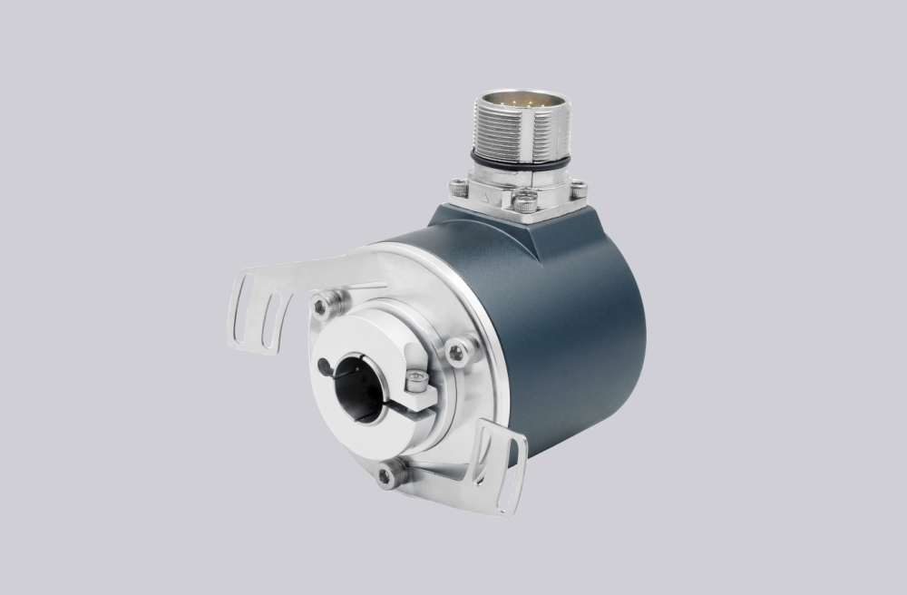
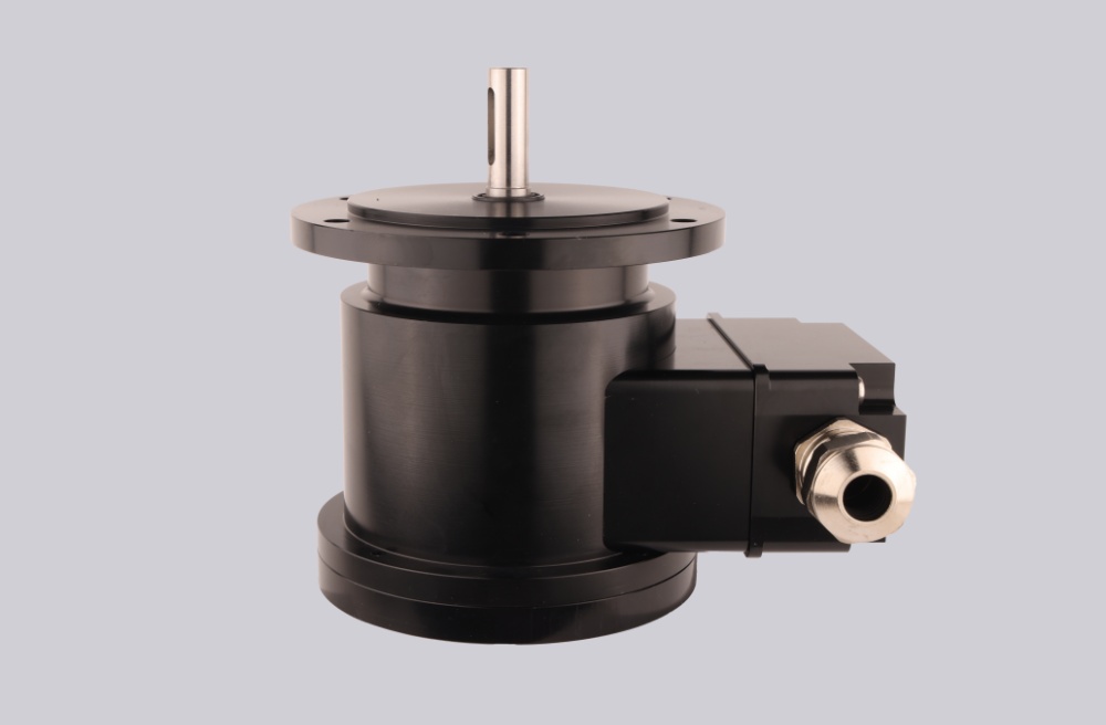
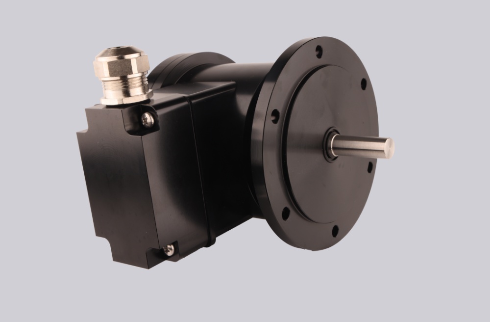
We developed a custom solution for the POG 9 G DN 1024 I / DN 500 I twin encoder, intended for heavy-duty systems where two independent incremental feedback channels must remain synchronized under vibration, thermal drift, long cable routing, and continuous high-speed operation. This is not a standard incremental encoder. It is a redundant feedback structure built around two isolated encoder systems, using:
- 1024 PPR output on the first channel
- 500 PPR output on the second channel
- HTL line-driver output with inverted signals
- EURO flange B10
- Ø11 mm shaft
- terminal-box connection
Typical production lead time: 15 working days.
The actual limitation in this structure is usually not encoder resolution. Instability normally appears first at:
- redundant channel synchronization
- grounding continuity inside the terminal box
- cable impedance over long HTL routing
- coupling torsion under heavy inertia
What Usually Fails First
In actual crane, rolling mill, and heavy-drive systems, the encoder optics rarely become the first failure point.
The weak points normally appear at:
- shaft vibration under high inertia
- terminal-box grounding instability
- thermal expansion affecting dual-channel phase consistency
- long-distance signal reflection
This becomes more visible above high rotational speed and elevated ambient temperature.
The encoder supports:
- output frequency ≤120 kHz
- operating speed ≤12000 rpm
- operating temperature up to +100 °C
- vibration resistance 10 g
- shock resistance 300 g
But once cable shielding or grounding impedance becomes unstable, pulse symmetry degradation usually appears before actual encoder failure.
Redundant Channel Logic
This configuration combines:
- one 1024 PPR feedback system
- one 500 PPR feedback system
inside the same housing.
The real integration risk is not pulse generation itself but whether the PLC or drive system can maintain stable interpretation between two independent feedback structures during thermal drift and mechanical vibration.
Typical instability points:
- phase skew between redundant channels
- inconsistent counter timing
- pulse edge degradation over long cable distance
- incorrect inverted-signal handling
Mechanical System Boundary
The encoder uses:
- EURO flange B10
- Ø11 mm stainless shaft
- aluminium die-cast housing
- rotor inertia 200 gcm²
- radial load ≤350 N
- axial load ≤250 N
This means coupling quality directly affects long-term signal stability.
In this structure, torsional vibration usually appears earlier than actual bearing failure.
Installation Notes
- Maintain shielding continuity through the terminal box
- Separate encoder routing from motor power cables
- Keep grounding impedance stable across long-distance cable runs
- Verify redundant-channel synchronization inside the PLC or drive
- Use proper heavy-duty flexible coupling for shaft torsion absorption
- Avoid rigid coupling under thermal expansion conditions
Key Data
- Model: POG 9 G DN 1024 I / DN 500 I
- Type: Twin incremental encoder
- Output structure: Dual independent systems
- Resolution 1: 1024 PPR
- Resolution 2: 500 PPR
- Output circuit: HTL line driver with inverted outputs
- Signals: K1, K2, K0 + inverted
- Frequency: ≤120 kHz
- Shaft: Ø11 mm stainless steel
- Flange: EURO flange B10
- Operating speed: ≤12000 rpm
- Protection: IP56
- Temperature: -30 °C to +100 °C
- Vibration: 10 g
- Shock: 300 g
- Explosion protection: II3G Ex nA T4 X / II3D Ex tD IP56 A22 T135°C X
- Connection: Terminal box
- Weight: Approx. 1.7 kg