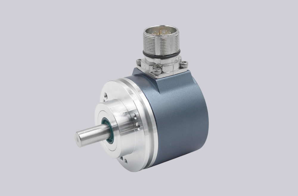
A custom compatible encoder solution can be provided for the POG 9G DN 500 I / DN 500 I twin incremental encoder configuration used in industrial drive monitoring and rotating machinery systems. This engineering service supports equipment operators who require compatible encoder configurations for maintenance, repair, or system integration. Through customized mechanical and electrical adaptation, a compatible encoder can normally be produced with a lead time of approximately 10–15 working days, allowing industrial equipment to return to operation efficiently.
Technical Overview of the POG 9G DN 500 I / DN 500 I Encoder
The POG 9G DN 500 I / DN 500 I represents a twin incremental encoder architecture integrating two independent sensing systems within one mechanical housing. Each sensing unit operates using an optical scanning principle in which a coded disc attached to the rotating shaft is detected by optical sensors that generate digital pulse signals.
Both encoder systems provide 500 pulses per revolution, allowing two identical feedback channels to operate simultaneously. This configuration is frequently used in industrial drive systems where redundant monitoring signals are required for operational reliability.
Twin encoder designs allow two separate signal outputs to be generated while sharing the same shaft rotation. This architecture improves monitoring capability and allows connection to multiple control systems when required.
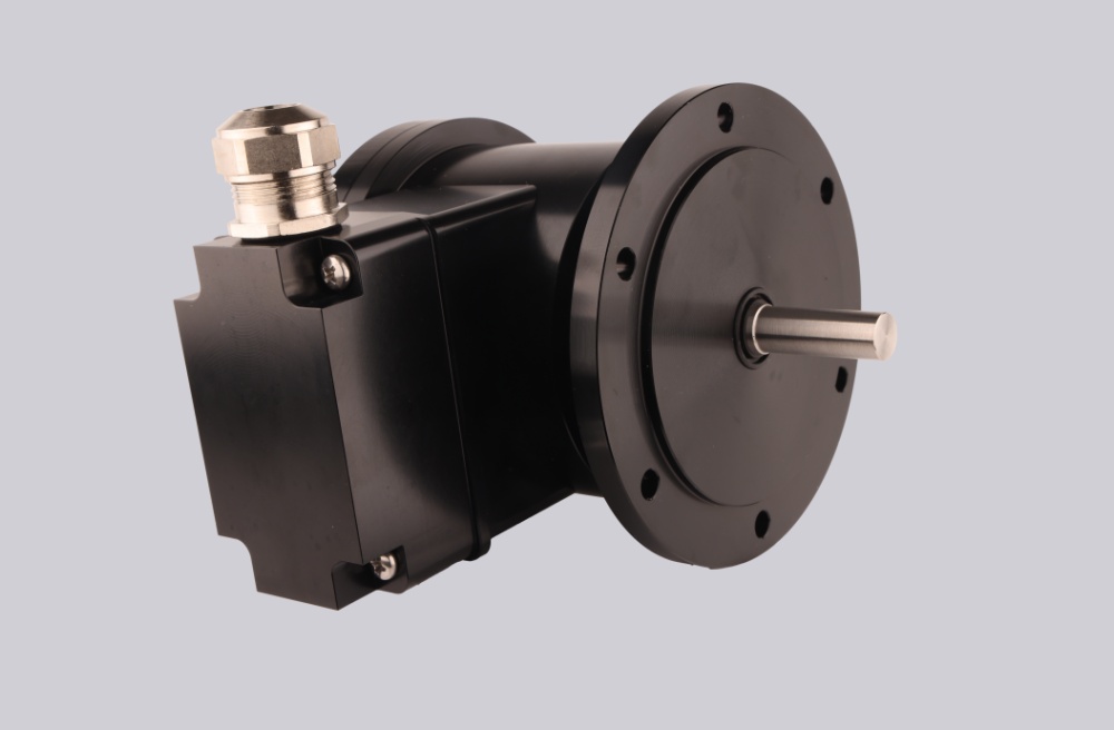
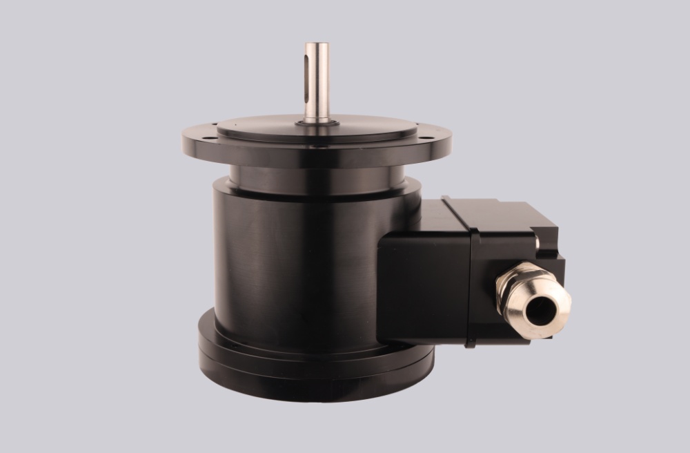
Industrial Integration Considerations
Installation of the POG 9G DN 500 I / DN 500 I encoder requires precise alignment between the encoder shaft and the machine drive shaft. Proper shaft coupling ensures that rotational movement is transferred accurately to both sensing systems.
Industrial installations may expose encoders to vibration and temperature variation. Flexible couplings and stable mounting structures help maintain signal stability under these conditions.
Electrical signal transmission should be implemented using shielded cables and proper grounding practices to reduce interference and maintain signal reliability.
Custom Compatible Encoder Solution
For systems currently using the POG 9G DN 500 I / DN 500 I configuration, a custom compatible encoder solution can be engineered to maintain compatibility with the existing mechanical and electrical installation.
Engineering compatibility typically includes matching shaft diameter, mounting flange dimensions, signal output configuration, and connector interfaces. Maintaining these parameters allows the compatible encoder to integrate directly into the existing control architecture.
Additional customization may include adjustments to signal interfaces or installation configuration depending on the specific requirements of the industrial application.
Lead Time and Custom Development
Compatible encoder solutions for the POG 9G DN 500 I / DN 500 I configuration can generally be manufactured within 10–15 working days, helping maintenance teams restore equipment operation without extended delays.
Typical Technical Parameters
| Parameter | Specification |
|---|---|
| Encoder Type | Twin Incremental Encoder |
| Resolution | 500 PPR / 500 PPR |
| Output Signals | K1, K2, K0 |
| Output Circuit | TTL / HTL |
| Supply Voltage | 5 VDC / 9–30 VDC |
| Shaft Diameter | 11 mm |
| Flange Type | EURO flange B10 |
| Protection Rating | IP56 |
| Operating Temperature | -30°C to +100°C |