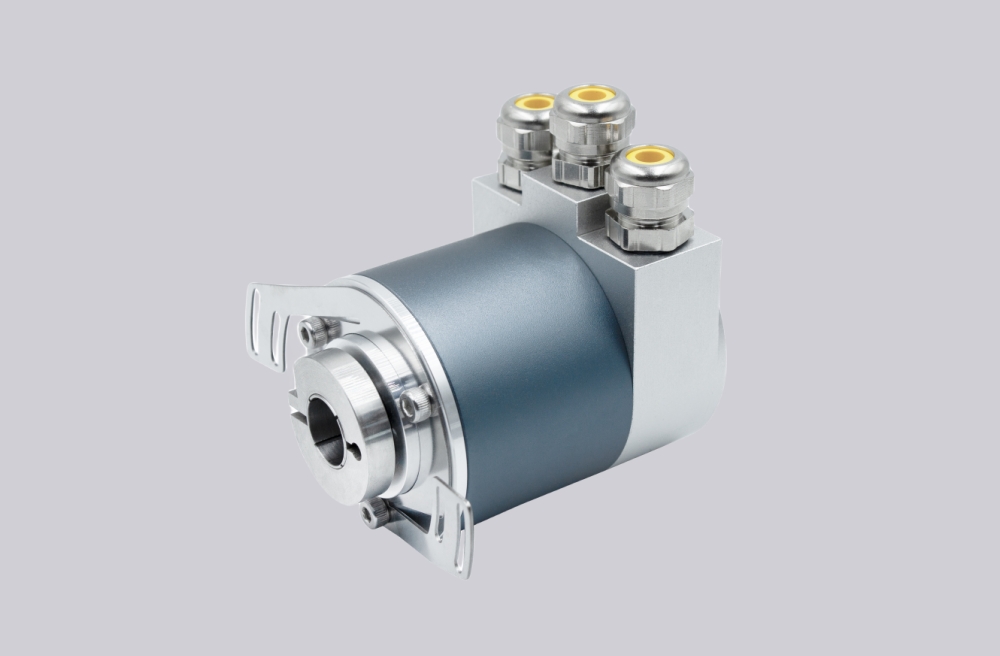
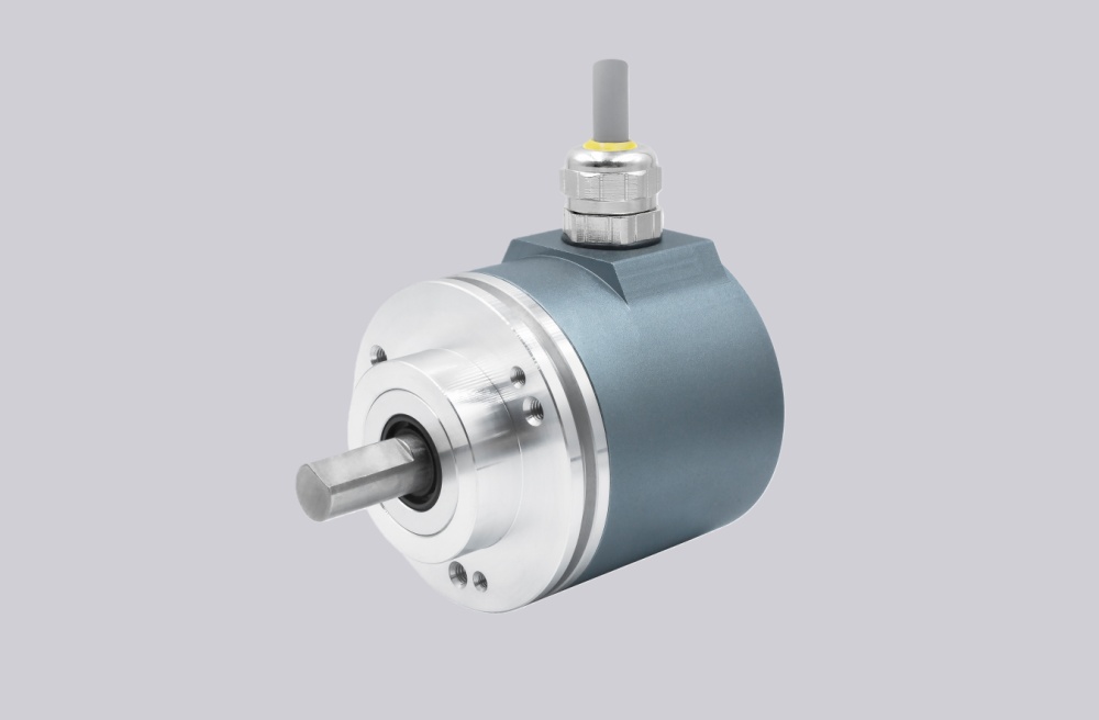
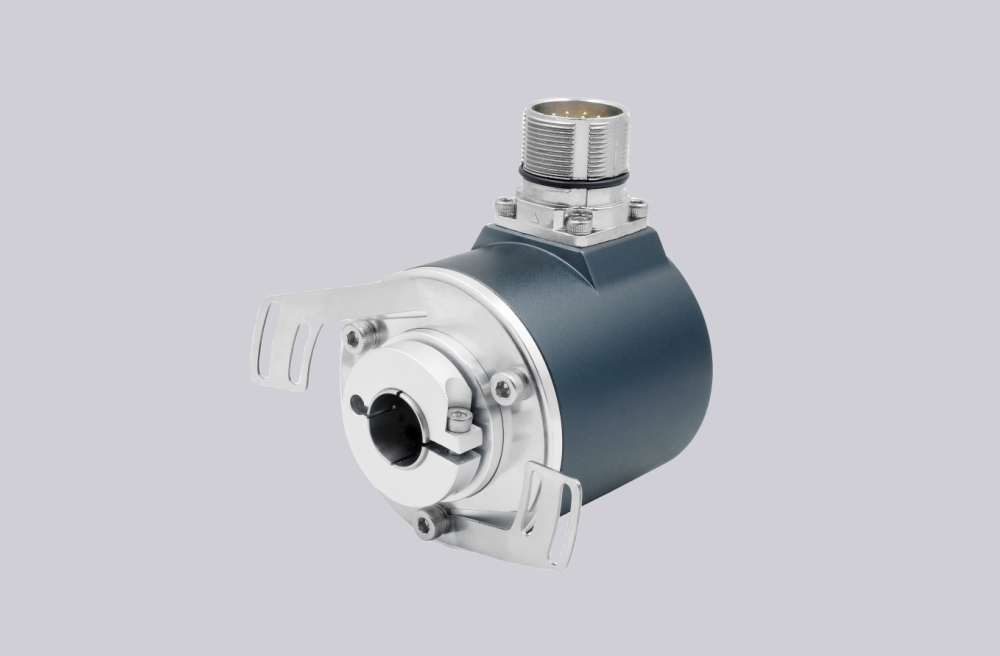
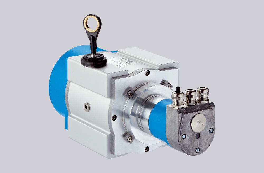
EncoderWorks can supply a custom compatible replacement for OCM-DPC1B-1213-Z10W-HFZ where the main engineering check is the combination of Profibus DP parameter mapping, square ATEX flange interchange, and ø10 mm solid-shaft alignment. In a mining encoder replacement, failure often appears after installation when the PLC accepts the bus node but reads an incorrect position value, loses diagnostics, or reports intermittent communication faults under drive noise. Typical production lead time: 15 working days.
This model is used as an absolute multiturn feedback device in hazardous mining environments where position retention, stainless-steel construction, and bus stability are more important than simple mechanical substitution. A compatible replacement must therefore be verified as a system component: the Profibus address, GSD configuration, resolution structure, preset behavior, counting direction, bus termination, shaft fit, and flange mounting surface all affect whether the encoder can return to service without PLC modification.
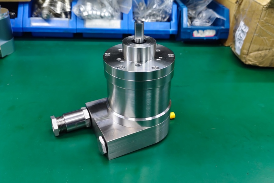
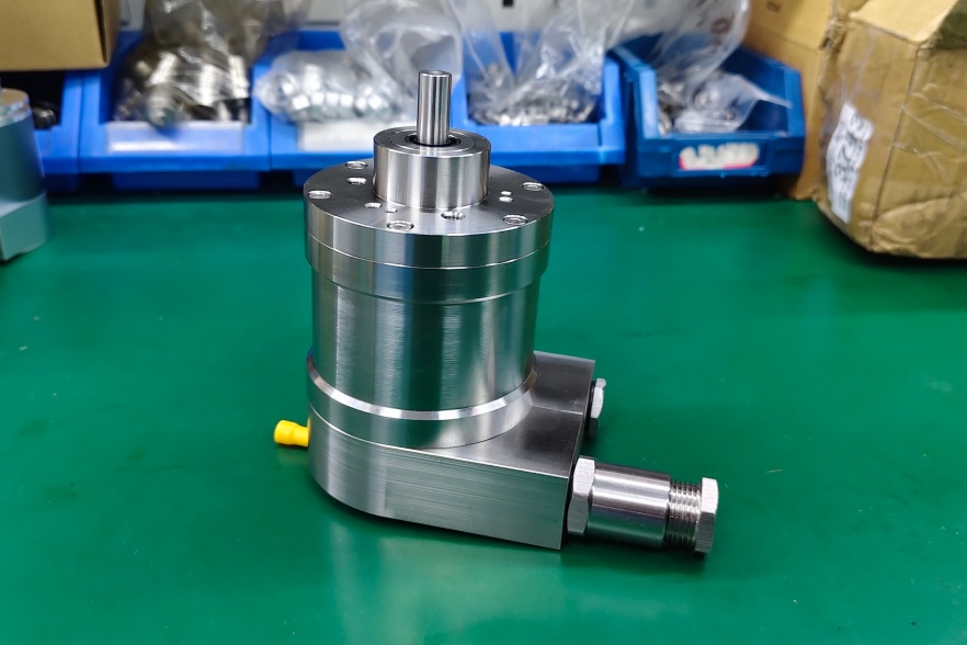
System Limits
The first limit is Profibus DP configuration. OCM-DPC1B-1213-Z10W-HFZ uses a Profibus DP interface with DPV0, DPV1, and DPV2 Class 2 profile support. During replacement, the encoder must be checked against the existing PLC hardware configuration, node address, parameterization data, and diagnostic expectations. If the address switch, terminal resistor, or GSD file does not match the installed system, the encoder may remain outside data exchange or may enter the network with unstable diagnostics.
The second limit is position scaling. The encoder uses 13-bit singleturn and 12-bit multiturn resolution, so the controller may depend on a specific physical resolution, gearing factor, preset value, and rotation direction. A replacement should not be approved only by total resolution. The actual position value must be tested through one full rotation and across multiturn travel to confirm that zero point, direction, and scaling remain consistent.
The third limit is EMC and bus integrity. Mining hoists, conveyors, winches, and heavy drive systems often place Profibus cabling close to inverter or motor power wiring. Even with a galvanically isolated Profibus data interface, shield discontinuity, incorrect grounding, or poor bus termination can produce intermittent faults. These faults may not appear during low-speed commissioning, but they can interrupt data exchange during acceleration, braking, or high-load switching.
Mechanical fit is also critical. The □80 mm square ATEX flange and ø10 mm solid shaft must be aligned without forcing the coupling. Excessive radial or axial load can reduce bearing life, while angular misalignment can create vibration and shaft stress even when the digital position data appears correct.
Wiring & Installation
Before startup, confirm bus-in and bus-out wiring, power polarity, shield continuity, and termination position. The Profibus A and B lines must follow the existing cabinet convention, and termination should be active only at the physical end of the segment. After wiring, verify online PLC diagnostics, node recognition, parameterization status, and stable position feedback.
For mechanical installation, clean the flange surface, check coupling depth, avoid shaft preload, and confirm that the cable or gland orientation does not create strain on the radial connection cap. In hazardous mining applications, the replacement should also preserve the required enclosure and sealing arrangement.
Custom Compatible Solution
EncoderWorks can build the replacement around the installed system requirements:
- Match Profibus DP communication, GSD configuration, node address behavior, and diagnostic response
- Adapt the square ATEX flange, ø10 mm solid shaft, radial connection layout, and stainless housing format
- Verify 13-bit singleturn, 12-bit multiturn, preset, direction, and scaling behavior before shipment
- Review shield grounding, bus termination, and mechanical load conditions for mining-duty reliability
Key Data
| Item | Data |
|---|---|
| Model | OCM-DPC1B-1213-Z10W-HFZ |
| Encoder type | Absolute multiturn encoder |
| Interface | Profibus DP |
| Profile | DPV0, DPV1, DPV2 Class 2 |
| Transmission rate | ≤12 Mbaud |
| Interface cycle time | ≥1 ms |
| Output driver | Profibus data interface, galvanically isolated |
| Supply voltage | 10–30 VDC |
| Current consumption | ≤230 mA at 10 VDC, ≤100 mA at 24 VDC |
| Sensor technology | Optical |
| Singleturn resolution | 13 bit |
| Multiturn resolution | 12 bit |
| Multiturn technology | Mechanical gearing, no battery |
| Code | Binary |
| Protection class | IP66/IP67 |
| Operating temperature | -40 °C to +70 °C |
| Flange | Square, □80 mm, ATEX |
| Shaft | Solid shaft, single flat |
| Shaft diameter | ø10 mm |
| Shaft length | 20 mm |
| Max shaft load | Axial 50 N, radial 50 N |
| Max mechanical speed | 3000 rpm |
| Housing material | Stainless steel V4A / 316L |
| Connection orientation | Radial |
| Connection type | 2 × blind plug, radial |
| Approval | CE + ATEX Zone 1 & 21 Mining |