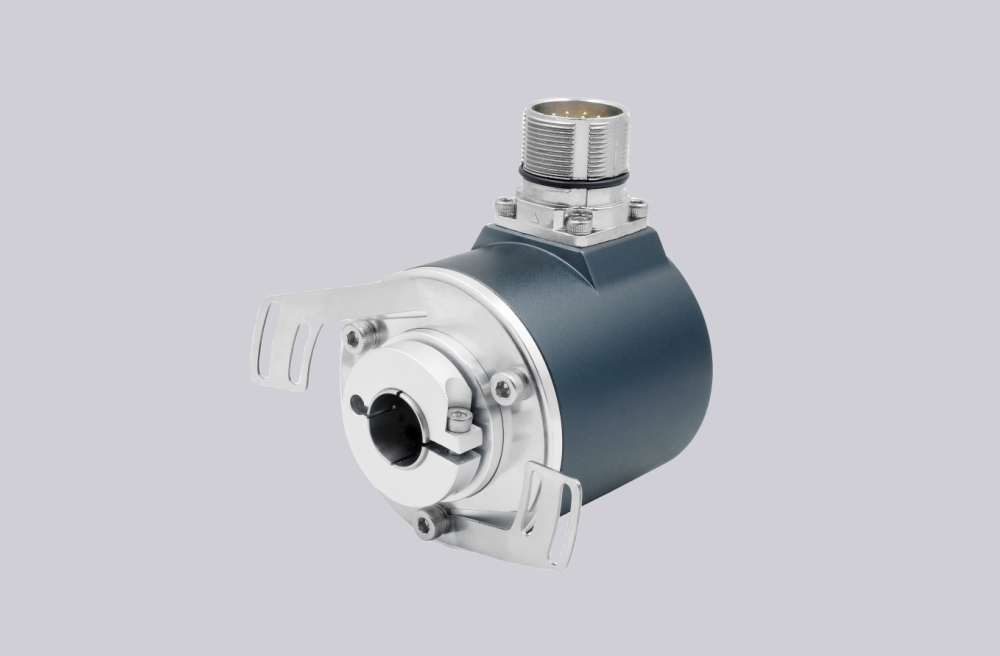



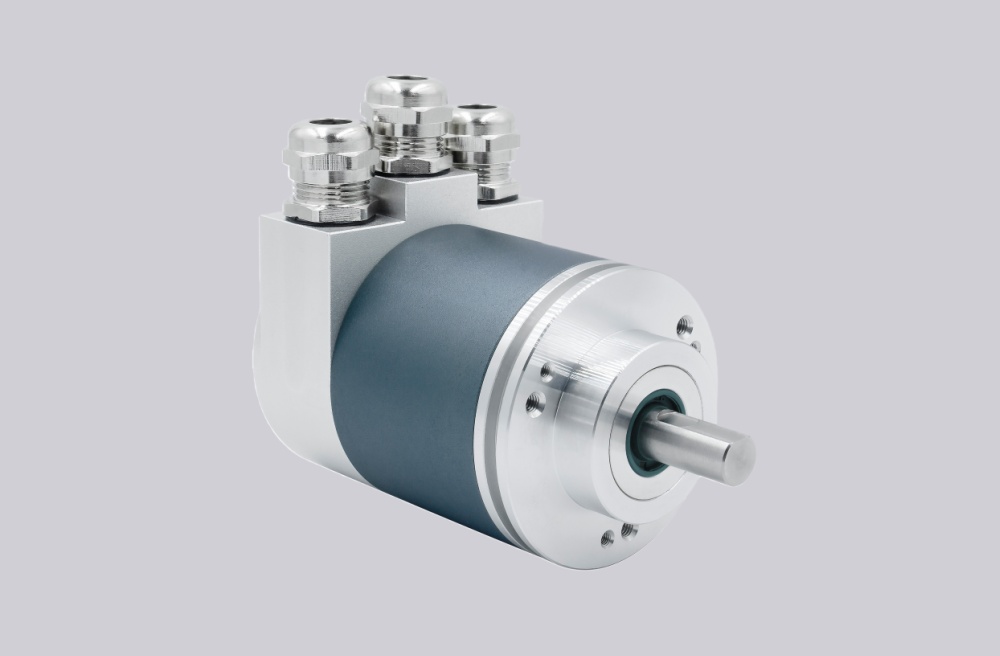
For OCF-DPC1B-1413-C100-H3E, EncoderWorks can provide a custom compatible replacement solution for hazardous-area Profibus absolute feedback systems where the key checks are DP address setting, bus termination, scaling data, ø10 mm solid-shaft coupling, and Zone 2 & 22 cable-gland installation. This model should not be treated like a Profinet encoder, because communication, diagnostics, node addressing, termination, and PLC parameter handling are all based on Profibus DP behavior. Typical production lead time: 15 working days.
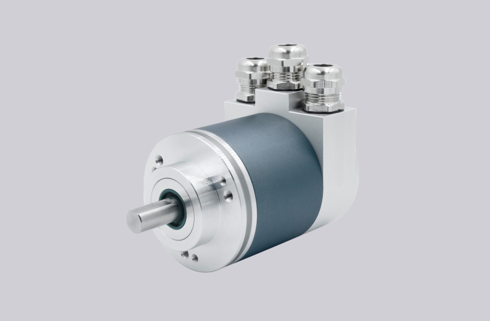
This configuration is used where an absolute multiturn encoder must provide reliable position data through a Profibus DP network in Zone 2 & 22 environments. The encoder combines 13-bit singleturn resolution, 14-bit multiturn mechanical gearing, binary code handling, a ø58 mm clamp flange, ø10 mm solid shaft, and a removable radial connection cap with three cable glands. Replacement work should focus on node number, terminal resistor status, bus in/out wiring, scaling parameters, preset behavior, counting direction, shaft coupling alignment, and EMC grounding.
System Limits
The first system limit is Profibus commissioning. The PLC must recognize the encoder with the correct GSD configuration, node address, profile behavior, resolution setting, gearing factor, preset value, and counting direction. If the encoder is powered and connected but the stored configuration does not match the replacement, the bus may run while the axis reads the wrong position.
The second limit is bus wiring and termination. This model uses bus-in and bus-out connections through the connection cap, with address selection and terminal resistor handling inside the cap. Wrong A/B bus polarity, missing termination, duplicate node address, or shield discontinuity can create intermittent diagnostics rather than a simple no-power fault.
The mechanical limit is the ø10 mm solid shaft and clamp flange. Coupling misalignment, axial preload, radial load, or an over-tightened mounting bracket can shorten bearing life or create position drift under vibration.
Wiring & Installation
Before replacement, record the Profibus node number, GSD file, profile setting, preset value, scaling data, velocity filter, counting direction, and limit-switch parameters from the existing PLC project. Also record the connection cap wiring for bus line A/B in, bus line A/B out, power supply, ground, shield, and terminal resistor status.
During installation, align the ø10 mm shaft coupling without axial force and keep the clamp flange square to the bracket. Route Profibus cables away from inverter output wiring, preserve shield continuity through the cable glands, and avoid ground loops between the encoder housing, machine frame, and cabinet earth. After startup, verify online device status, actual position value, direction, preset response, diagnostics, and repeatability over several machine cycles.
Custom Compatible Solution
EncoderWorks can configure the replacement around the installed Profibus and mechanical interface:
- Match Profibus DP communication, node addressing, GSD configuration, scaling, preset, counting direction, and diagnostics
- Preserve 13-bit singleturn and 14-bit multiturn absolute position behavior with binary code handling
- Adapt the ø58 mm clamp flange, ø10 mm solid shaft, shaft coupling, and radial connection-cap envelope
- Review bus A/B polarity, terminal resistor status, shield grounding, cable-gland sealing, and Zone 2 & 22 installation limits
Key Data
| Item | Data |
|---|---|
| Model | OCF-DPC1B-1413-C100-H3E |
| Encoder type | Absolute multiturn encoder |
| Interface | Profibus DP |
| Profile | DPV0, DPV1, DPV2 Class 2 |
| Resolution | 13-bit singleturn + 14-bit multiturn |
| Code | Binary |
| Supply voltage | 10–30 VDC |
| Output driver | Profibus data interface, opto-isolated |
| Flange | Clamp, ø58 mm |
| Shaft | ø10 mm solid shaft, single flat |
| Connection | Radial, 3× cable gland Zone 2+22 |
| Protection | Shaft IP65, housing IP66/IP67 |
| Approval | CE + ATEX Zone 2 & 22 |