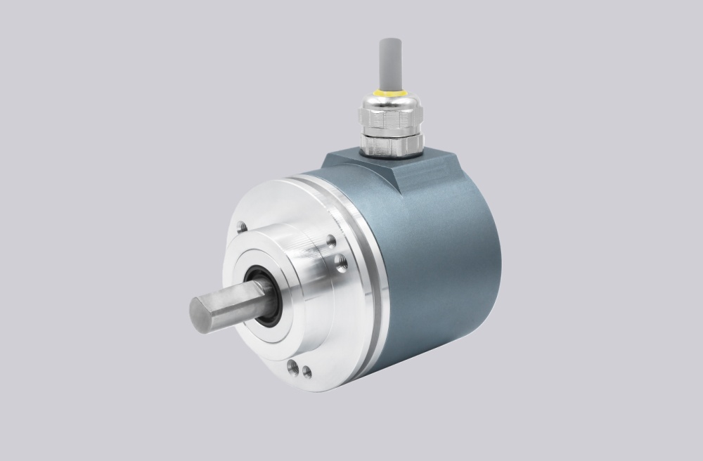
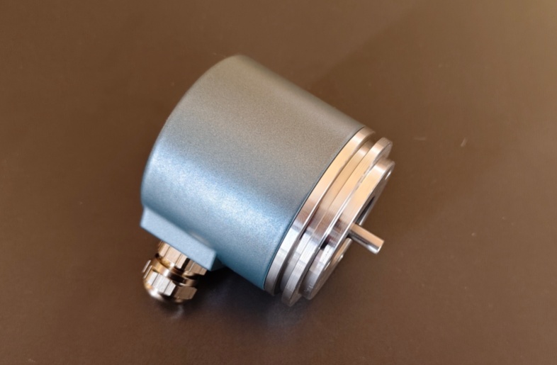
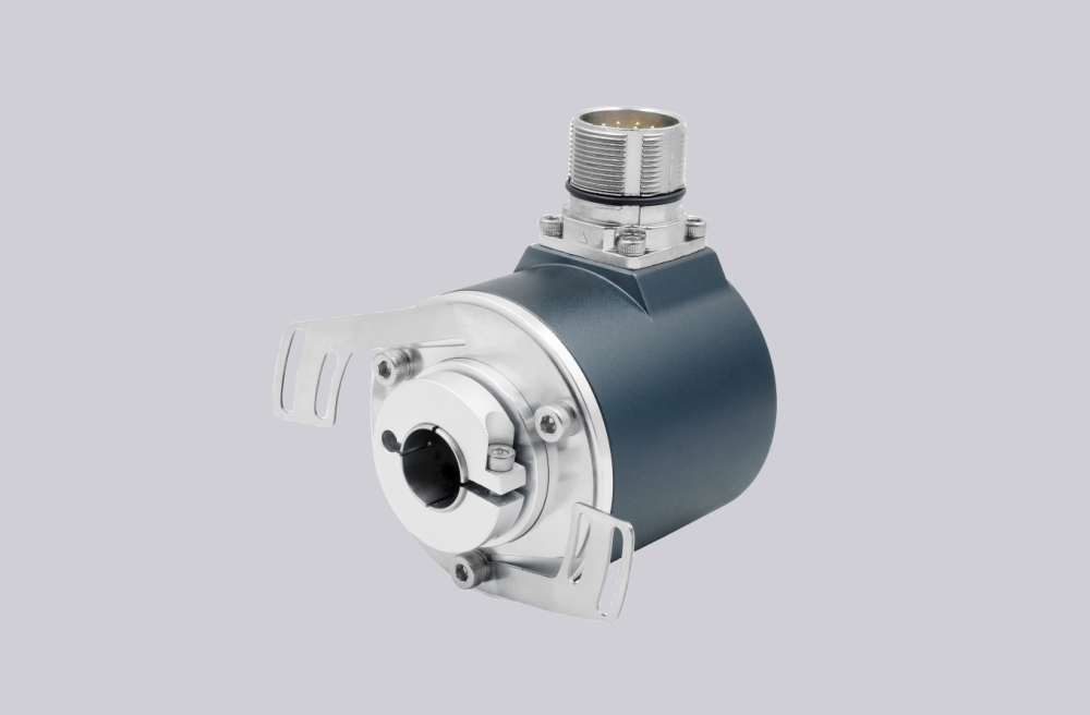
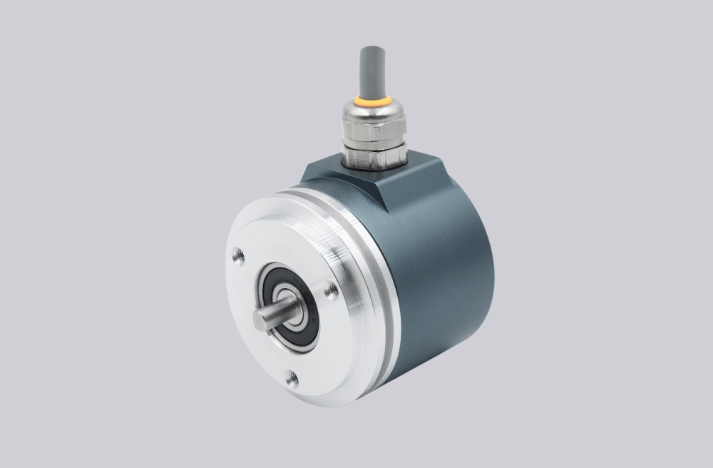
EncoderWorks can configure OCD-PPA1B-0810-B15S-PRT as a custom compatible replacement solution for absolute multiturn feedback where 18-bit Bit Parallel data, Binary code interpretation, latch timing, DIR logic, and M27 26-pin radial mapping must remain aligned with the installed controller. The failure boundary is not only the 10–30 V push-pull output level, but also bit order, multiturn data significance, connector pinout, sampling timing, Ø15 mm blind-hollow shaft fit, and radial connector clearance. Typical production lead time: 15 working days.
This model is used where the control system reads an absolute multiturn position word through discrete parallel data lines. A compatible replacement must preserve the 10-bit singleturn and 8-bit multiturn code combination, push-pull output behavior, Binary data interpretation, latch input function, counting direction input, radial connector orientation, and Ø15 mm blind-hollow mechanical interface.


System Limits
The first system boundary is the 18-bit Binary parallel data structure. OCD-PPA1B-0810-B15S-PRT uses Bit 1 to Bit 18 as discrete position data lines, combining singleturn and multiturn information in the controller’s absolute word. If the replacement changes bit order, reverses data significance, removes the latch function, changes DIR behavior, or uses a different code-format assumption, the controller can receive stable electrical signals but calculate the wrong position. Typical failure symptoms include position jumps, reversed travel, incorrect multiturn count, unstable end-position logic, or repeatable offset after power cycling.
The second boundary is the latch, DIR, and M27 26-pin connector relationship. The controller must sample the parallel word at the correct logic point, so latch input behavior, direction input status, supply reference, GND integrity, and connector pin mapping must remain consistent. A replacement can fail even when voltage and resolution match if the latch line is left floating, the DIR line is wired with the wrong state, or one data bit is shifted by a single pin.
Wiring & Installation
Before replacement, confirm the full installed model code, 10–30 V supply, push-pull parallel input compatibility, 18-bit data mapping, Binary code handling, latch input use, DIR input logic, M27 26-pin radial connector orientation, and controller sampling method. Do not treat this as a Profibus or incremental replacement, because the controller is reading a complete absolute multiturn word rather than a configured bus object or A/B/Z pulse train.
The blind-hollow shaft installation must also be checked carefully. The Ø15 mm hollow interface, clamping condition, torque restraint, shaft insertion depth, radial connector clearance, static or dynamic misalignment, and shield continuity can affect bearing load and long-term stability. Poor clamping, shaft offset, connector stress, or grounding discontinuity can cause mechanical drift, intermittent data faults, or early bearing wear.
Custom Compatible Solution
- Match 10-bit singleturn plus 8-bit multiturn Bit Parallel feedback with Binary output behavior
- Preserve Bit 1–18 mapping, latch function, DIR logic, supply reference, and M27 26-pin connector assignment
- Adapt the Ø15 mm blind-hollow shaft, 58 mm flange class, radial connector orientation, and mechanical mounting boundary
- Review controller sampling timing, cable shielding, grounding, connector clearance, and shaft misalignment before shipment
Key Data
| Item | Data |
|---|---|
| Model | OCD-PPA1B-0810-B15S-PRT |
| Encoder type | Absolute multiturn rotary encoder |
| Interface | Bit Parallel |
| Output driver | Push-Pull |
| Supply voltage | 10–30 VDC |
| Code | Binary |
| Singleturn resolution | 10 bit |
| Multiturn resolution | 8 bit |
| Total data width | 18-bit parallel data |
| Multiturn technology | Mechanical gearing, no battery |
| Manual function | Counting direction via cable or connector |
| Connection | M27 male, 26 pin |
| Connection orientation | Radial |
| Shaft / flange | Blind hollow, Ø15 mm shaft, 58 mm B flange class |
| Protection class | IP66 / IP67 shaft and IP65 housing boundary requires confirmation against installed version |
| Key replacement checks | Bit 1–18 mapping, Binary code interpretation, latch timing, DIR logic, push-pull input match, M27 26-pin wiring, Ø15 mm blind-hollow shaft fit |