




For OCD-PPA1G-0012-B140-CAW, EncoderWorks can provide a custom compatible replacement solution for 12-bit parallel absolute feedback systems where the key checks are bit-line mapping, latch timing, DIR logic, and ø14 mm blind-hollow shaft fit. The replacement must be verified at the controller input, because one swapped bit, unstable latch signal, or reversed direction line can create valid-looking but incorrect position data. Typical production lead time: 15 working days.
This model is used where a PLC input card, counter module, or legacy controller reads absolute angular position through individual parallel lines instead of SSI, CANopen, or Profibus. Replacement work should therefore treat the encoder as part of a wiring, sampling, and mechanical alignment system. The push-pull output level, Gray-code reading, 12-bit wiring order, latch behavior, direction input, axial cable exit, flange seating, and blind-hollow shaft engagement must be checked together.
System Limits
The main electrical limit is 12-bit parallel signal integrity. Each bit line must be wired to the correct controller input and remain stable under machine noise. A high-order bit fault can create a large angular jump, while a low-order bit fault may appear as repeated indexing drift. The controller must also read the value as Gray code, not straight binary.
Latch timing is the second failure boundary. If the PLC samples the bit pattern while the shaft is crossing a transition point, it may capture a false intermediate value. The latch line should match the controller scan cycle and the actual moment when position data is required.
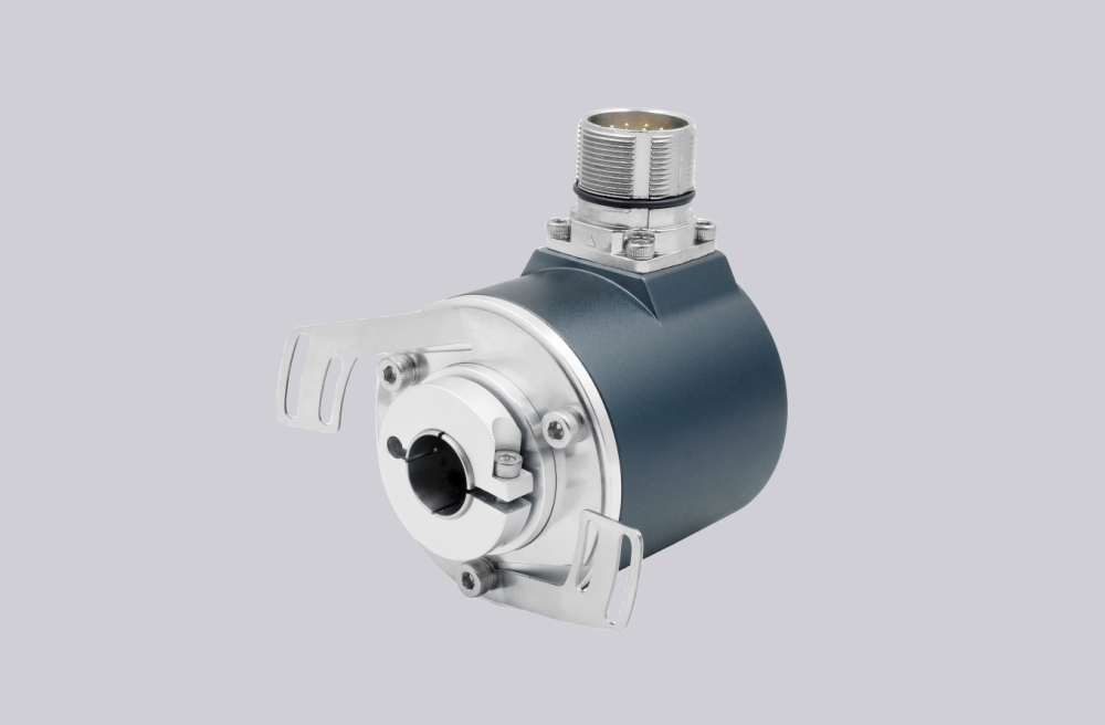
The mechanical limit is the ø14 mm blind-hollow shaft interface. The bore, 30 mm shaft depth, and ø58 mm flange must be installed without radial preload or dynamic misalignment. Shielding and cable routing should also be reviewed, because parallel cables are sensitive to noise from inverter, motor, brake, or solenoid wiring.
Wiring & Installation
Before removing the existing encoder, record the cable assignment for Bit 1 through Bit 12, Latch, DIR, supply, and GND. The replacement should be wired channel by channel rather than by assumed color order.
After wiring, rotate the shaft slowly and confirm that the controller value changes smoothly in the expected direction. Then test the latch function under the real machine scan condition. If the application uses cam windows, indexing stops, or position-based interlocks, check those switching points again after mechanical zero alignment.
Custom Compatible Solution
EncoderWorks can configure the replacement around the installed machine requirements:
- Match 12-bit parallel output, push-pull voltage level, Gray-code reading, and controller input mapping
- Adapt the ø58 mm blind-hollow flange, ø14 mm bore, axial cable exit, and 1 m cable length
- Verify Latch, DIR, cable color mapping, and controller-side value direction before shipment
- Review shielding, grounding, cable routing, and blind-hollow shaft load for stable operation
Key Data
| Item | Data |
|---|---|
| Model | OCD-PPA1G-0012-B140-CAW |
| Encoder type | Absolute singleturn encoder |
| Interface | Bit Parallel |
| Resolution | 12 bit singleturn |
| Code | Gray |
| Output driver | Push-Pull |
| Supply voltage | 10–30 VDC |
| Flange | Blind Hollow, ø58 mm |
| Shaft | ø14 mm blind hollow shaft, 30 mm depth |
| Connection | Axial, 1 m PVC cable |
| Protection class | IP65 |
| Approval | CE |






