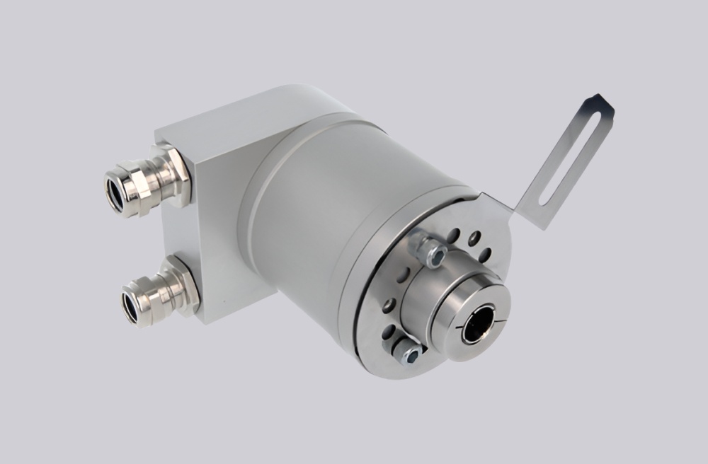
When replacing OCD-EEC1B-1216-B10A-PSM, the engineering match is not only the 16-bit/12-bit absolute position range; it also depends on EtherNet/IP CIP behavior, DLR network continuity, IP-address handling, ø10 mm blind-hollow shaft fit, and three-M12 port wiring. EncoderWorks can configure a custom compatible replacement solution for this model when the installed PLC, network topology, and mechanical clamp interface must remain unchanged. Typical production lead time: 15 working days.
This configuration is used where an absolute multiturn encoder must provide binary position data through an EtherNet/IP network rather than through parallel bits, SSI clock/data, or Profibus telegrams. The encoder combines 16-bit singleturn resolution, 12-bit multiturn mechanical gearing, optical sensing, CIP communication, DLR support, velocity, acceleration and temperature values, a ø58 mm blind-hollow flange, a ø10 mm blind-hollow shaft, and radial 3×M12 connection. Replacement work should focus on IP address, device configuration, assembly data, scaling, preset, counting direction, DLR ring behavior, shield grounding, and hollow-shaft clamping.


System Limits
The first system limit is EtherNet/IP commissioning. The controller must preserve the expected IP address, device identity, CIP profile behavior, assembly data, scaling parameters, time base, velocity filter, preset value, and counting direction. If the encoder appears online but the data layout or scaling differs, the PLC can receive stable network data while converting it into the wrong machine position.
The second limit is network wiring. This model uses Ethernet ports for Tx/Rx pairs and a separate M12 power connector. Wrong D-coded Ethernet pin mapping, poor shield continuity, or broken DLR ring behavior can create intermittent diagnostics instead of a simple no-communication fault.
The mechanical limit is the ø10 mm blind-hollow shaft and the IP54 housing installation. Shaft insertion depth, clamp force, static and dynamic misalignment, and cable exit clearance must be controlled. A forced fit or housing movement can create repeatability drift even when the EtherNet/IP data remains valid.
Wiring & Installation
Before replacement, record the EtherNet/IP IP address, device name or identity settings, EDS/project configuration, assembly format, scaling, preset value, counting direction, velocity settings, and diagnostic behavior from the PLC project. Also record the three M12 assignments: Ethernet port 1, power connector, and Ethernet port 3.
During installation, confirm the ø10 mm blind-hollow shaft fit without forcing the clamp. Route Ethernet and power cables away from inverter output wiring, maintain shield continuity through the M12 connectors, and avoid ground loops between the encoder housing, machine frame, and cabinet earth. After startup, verify network recognition, DLR status, actual position value, direction, preset response, diagnostic bits, and repeatability over several machine cycles.
Custom Compatible Solution
EncoderWorks can configure the replacement around the installed EtherNet/IP and mechanical system:
- Match EtherNet/IP CIP communication, IP addressing, DLR behavior, assembly data, diagnostics, scaling, preset, and counting direction
- Preserve 16-bit singleturn plus 12-bit multiturn binary absolute position behavior with velocity, acceleration, and temperature data handling
- Adapt the ø58 mm blind-hollow flange, ø10 mm blind-hollow shaft, radial 3×M12 connection layout, and rotary-switch access
- Review Tx/Rx pair mapping, shield grounding, cable routing, hollow-shaft clamping, misalignment, and IP54 housing limits
Key Data
| Item | Data |
|---|---|
| Model | OCD-EEC1B-1216-B10A-PSM |
| Encoder type | Absolute multiturn encoder |
| Interface | EtherNet/IP |
| Profile | CIP, with DLR support |
| Resolution | 16-bit singleturn + 12-bit multiturn |
| Code | Binary |
| Supply voltage | 10–30 VDC |
| Output driver | Ethernet |
| Flange | Blind Hollow, ø58 mm |
| Shaft | ø10 mm blind hollow shaft, depth 30 mm |
| Connection | Radial, 3×M12 with rotary switches |
| Protection | Shaft IP65, housing IP54 |
| Operating temperature | -40°C to +85°C |
| Approval | CE |