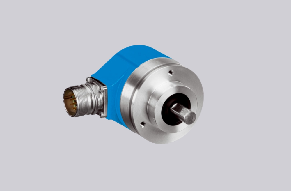
EncoderWorks can configure OCD-DPC1B-1416-S120-H3P as a custom compatible replacement solution for absolute multiturn Profibus DP feedback where node address, bus termination, 30-bit position structure, Class 2 parameter mapping, and Ø12 mm solid-shaft synchro-flange fit must remain aligned with the installed PLC project. The failure boundary is not only the 10–30 VDC supply, but also bus-in / bus-out polarity, configuration-file compatibility, preset behavior, counting direction, connection-cap termination logic, and coupling alignment. Typical production lead time: 15 working days.
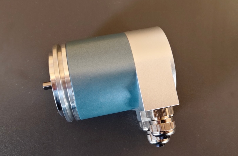
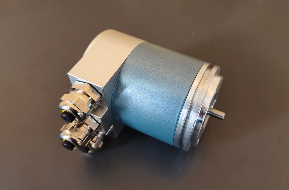
This model is used where the control system reads high-resolution absolute multiturn position over a Profibus DP network. A compatible replacement must preserve the 16-bit singleturn and 14-bit multiturn position structure, Binary position handling inside the bus device, node number, termination logic, configuration-file compatibility, radial 3-gland wiring layout, and Ø12 mm solid-shaft mechanical interface.
System Limits
The first system boundary is the Profibus DP network configuration. OCD-DPC1B-1416-S120-H3P uses a Profibus DP interface with Class 2 functions, so the PLC project must see the same device behavior, node address, resolution parameter, gearing factor, counting direction, preset function, velocity scaling, limit-switch behavior, diagnostic response, and process-data expectation. If the replacement is installed with a wrong node number, incompatible configuration file, different parameter length, wrong preset behavior, or mismatched direction setting, the network may still detect a device but the axis can report wrong position, wrong direction, incorrect multiturn value, missing diagnostics, or unstable commissioning status.
The second boundary is the Profibus physical layer and removable connection cap. Bus line A/B, bus-in / bus-out continuity, supply reference, GND, shield handling, terminal resistor status, and outgoing-bus behavior must match the existing topology. A correct encoder can still fail if the terminal resistor is enabled at the wrong point, the outgoing bus is unintentionally cut, A/B is reversed, shield continuity is poor, or the cable-gland arrangement creates intermittent grounding or routing stress.
Wiring & Installation
Before replacement, confirm the full installed model code, Profibus DP node address, transmission-rate setting, configuration-file requirement, Class 2 parameter use, preset requirement, counting direction, velocity scaling, diagnostic mapping, limit-switch use, and terminal resistor position. Do not treat this as a singleturn Profibus, Bit Parallel, EtherNet/IP, or incremental replacement, because the controller is reading a configured multiturn Profibus device rather than a shorter position word, separate data bits, an Ethernet object, or A/B/Z pulses.
The solid-shaft installation must also be checked carefully. The Ø12 mm shaft, 20 mm shaft length, 58 mm synchro-flange interface, coupling type, shaft insertion depth, radial connection-cap clearance, axial load, radial load, and alignment accuracy can affect long-term stability. Poor coupling alignment, excessive side load, loose cable glands, shield discontinuity, or connection-cap stress can cause bus dropouts, mechanical drift, intermittent diagnostics, or early bearing wear.
Custom Compatible Solution
- Match Profibus DP device behavior, 16-bit singleturn plus 14-bit multiturn feedback, node address range, and Class 2 parameter expectations
- Preserve bus-in / bus-out A/B wiring, terminal resistor logic, GND reference, shield continuity, and supply wiring
- Adapt the Ø12 mm solid shaft, 20 mm shaft length, 58 mm synchro-flange class, radial 3-gland connection cap, and mechanical mounting boundary
- Review configuration-file compatibility, preset direction, velocity scaling, diagnostics, terminal-resistor position, cable-gland routing, and shaft coupling alignment before shipment
Key Data
| Item | Data |
|---|---|
| Model | OCD-DPC1B-1416-S120-H3P |
| Encoder type | Absolute multiturn rotary encoder |
| Interface | Profibus DP |
| Profile / class | DPV0, DPV1, DPV2 Class 2 |
| Supply voltage | 10–30 VDC |
| Output driver | Profibus data interface, galvanically isolated via opto-couplers |
| Sensor technology | Optical |
| Singleturn resolution | 16 bit |
| Multiturn resolution | 14 bit |
| Total position structure | 30-bit absolute multiturn data |
| Code | Binary |
| Multiturn technology | Mechanical gearing, no battery |
| Transmission rate | Up to 12 Mbaud class boundary |
| Manual functions | Address selector 0–99 and terminal resistor via connection cap |
| Programming functions | Resolution, gearing factor, velocity scaling and filter, preset, counting direction, limit switches, node number, teach-in, diagnosis |
| Connection | 3 × cable gland connection cap |
| Connection orientation | Radial |
| Shaft / flange | Solid shaft, Ø12 mm × 20 mm, 58 mm S synchro flange class |
| Protection class | IP65 shaft and IP65 housing boundary requires confirmation against installed version |
| Key replacement checks | Node address, bus termination, configuration file, bus A/B mapping, Class 2 parameters, preset, direction, 30-bit position structure, Ø12 mm solid-shaft coupling fit |