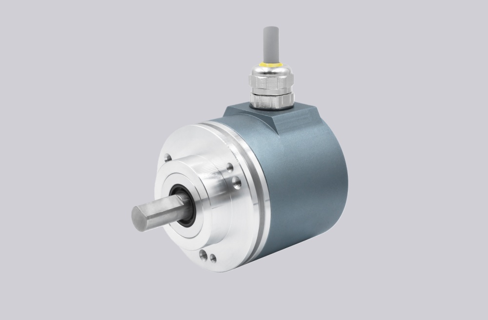
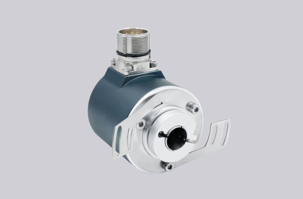
For HSD352048KCE, EncoderWorks can provide a custom compatible replacement solution for heavy-duty hollow-shaft incremental feedback systems where the key checks are 2048 PPR counter frequency margin, dual isolated ABZ signal matching, 1-1/4" bore fit, and 8.5" C-Face tether preload. This version should not be treated like an AB-only or isolated-bore encoder, because it uses a non-isolated bore and provides dual isolated differential ABZ outputs for redundant feedback paths. Typical production lead time: 15 working days.
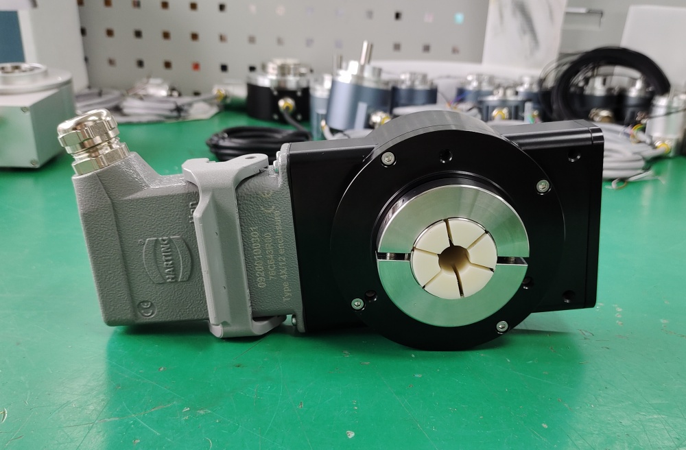
This model belongs to the HSD35 heavy-duty optical incremental encoder series. In the HSD352048KCE configuration, the encoder provides 2048 pulses per revolution, a 1-1/4" non-isolated hollow bore, an 8.5" C-Face tether with 1/2" bolt, and dual isolated differential ABZ outputs based on the 7272 5–26 VDC input / 5–26 V output format. Replacement work should focus on both output channels, A/A-, B/B-, Z/Z- wiring, counter decoding, index recognition, shaft clamping, tether alignment, and grounding behavior.
System Limits
The main electrical limit is dual isolated output compatibility. If one channel is used by the drive and the other by a PLC, monitor, or safety system, both outputs must preserve the same pulse count, A/B phase direction, Z index behavior, and voltage level. A single-output replacement may run the drive but leave the second feedback path unavailable.
The second limit is counter frequency margin. At 2048 PPR, the actual input frequency depends on shaft speed and x1, x2, or x4 quadrature decoding. The counter should be checked against the 200 kHz data and index frequency limit, A/B phase tolerance, and Z pulse recognition.
The mechanical limit is the 1-1/4" non-isolated hollow bore and 8.5" C-Face tether. The bore must fit the shaft without forcing the clamp, while the tether should stop housing rotation without side-loading the bearings. Because the bore is not electrically isolated, shaft grounding and drive-induced current paths should also be reviewed.
Wiring & Installation
Before removing the existing encoder, record how both isolated output channels are used. Check the 10-pin connector wiring for Common, Signal A, Signal B, Signal Z, Vcc, Signal A_, Signal B_, and Signal Z_, and confirm whether both receiving devices require independent feedback.
After installation, rotate the shaft slowly and confirm that A leads B for clockwise shaft rotation when viewed from the clamp end. Then check Z index position, pulse count, direction trend, redundancy behavior, tether movement, and counter stability at operating speed.
Custom Compatible Solution
EncoderWorks can configure the replacement around the installed drive and counter system:
- Match 2048 PPR dual isolated differential ABZ output and 7272 driver behavior
- Adapt the 1-1/4" non-isolated hollow bore, clamp fit, 8.5" C-Face tether, and 1/2" bolt mounting
- Verify A/B phase direction, Z index behavior, quadrature decoding mode, and both output-channel assignments
- Review 10-pin connector wiring, shield grounding, cable routing, shaft grounding, and tether preload
Key Data
| Item | Data |
|---|---|
| Model | HSD352048KCE |
| Encoder type | Heavy-duty optical incremental encoder |
| Resolution | 2048 PPR |
| Signal format | Dual isolated differential ABZ |
| Output circuit | Same as code 7: 7272, 5–26 VDC input, 5–26 V output |
| Bore | 1-1/4" non-isolated hollow bore |
| Mounting | 8.5" C-Face tether with 1/2" bolt |
| Max frequency | 200 kHz data and index |
| Max speed | 6000 RPM |
| Connection | 10-pin latching industrial connector |
| Protection class | IP67, IP64 above 5000 RPM |
| Connector rating | IP65 |