EncoderWorks develops a concise custom compatible solution for CEV65S-50004, focused on preserving the original singleturn parallel Gray-code output through the axial 25-pin SUB-D connector. The replacement fails when the controller reads the 8192-step absolute word with the wrong O_D0–O_D15 mapping, latch timing, Preset1 input, or Gray-code interpretation. Typical production lead time: 15 working days.
Where the System Fails First
The controller reads CEV65S-50004 as a singleturn parallel absolute position word. The pinout assigns O_D0 to O_D15 as data outputs, then places Direction IN on pin 17, Preset1_IN on pin 18, I_Latch on pin 20, RS485 programming lines on pins 22 and 23, supply voltage on pin 24, and ground on pin 25. That makes this model different from wider 24-bit parallel multiturn variants: the risk is 16-bit Gray-code word capture, not a full multiturn output map.
This replacement fails when the encoder is mechanically installed correctly but the controller samples the Gray-code word at the wrong latch moment or treats the singleturn value as a different scaling structure.
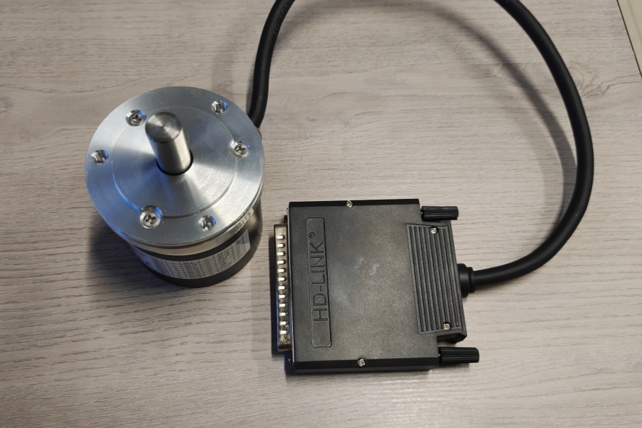
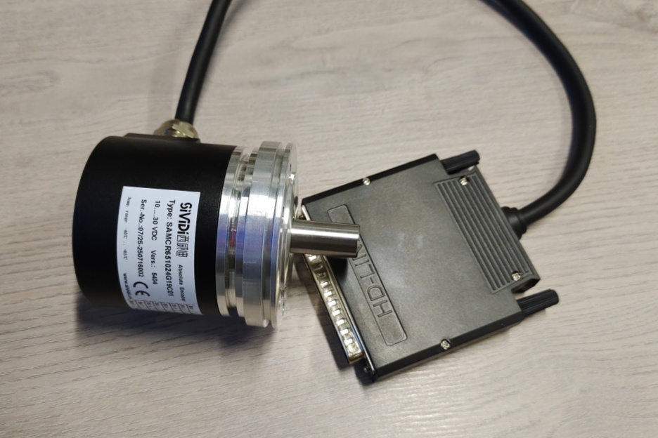
The main failure points are direct:
- Wrong O_D0–O_D15 mapping → corrupted Gray-code position
- Latch timing error → unstable sampled value
- Preset1 wiring mismatch → false reference position
- Direction input error → reversed counting behavior
- Axial SUB-D strain → intermittent bit-level faults
- RS485 programming wires mixed with data outputs → commissioning risk
A stable replacement must first reproduce the original 8192-step singleturn Gray-code behavior before the mechanical fit can be considered successful.
Connector and Mechanical Boundary
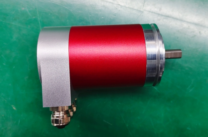
The drawing shows a ZB36 flange, 10FL / 19.5 shaft, and an axial 25-pin SUB-D connector. This axial connector layout changes the field risk: rear clearance, cable pull, and connector shell stability become part of the signal boundary. A loose SUB-D shell or strained rear cable can create random bit errors before the encoder body itself shows any hard failure.
For CEV65S-50004, the practical replacement boundary is SUB-D 25-pin Gray-code mapping plus latch capture reliability. The controller must read the same singleturn absolute word, with the same Direction and Preset1 behavior, under the same cabinet wiring conditions.
Installation Notes
- Keep the model format as CEV65S-50004
- Match the alternative reference 170-50004 where required
- Map O_D0–O_D15 by signal name
- Confirm Gray-code decoding at the controller side
- Check I_Latch on pin 20 before startup
- Verify Direction and Preset1 logic
- Protect the axial SUB-D connector from rear cable pull
- De-energize the system before wiring or connector work
Key Data
- Model: CEV65S-50004
- Alternative reference: 170-50004
- Type: Absolute rotary encoder
- Interface: Parallel push-pull
- Code: Gray
- Resolution: 8192 steps / revolution
- Revolutions: 1
- Supply voltage: 11–27 VDC
- Output level: 11–27 VDC
- Flange: ZB36
- Shaft: 10FL / 19.5
- Connector: SUB-D 25-pin
- Connector position: Axial
- Protection: IP65
- Temperature range: -20 °C to +70 °C
- Options: F/R, Latch, Preset1, Programmable
- Pinout: ST2755A
- Parameter file: CEV65S-50004
- Drawing: 04-CEV65S-M0026
- Firmware: 4376AD