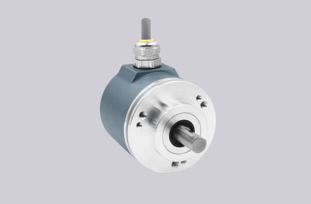
We developed a custom solution for CEV65M-10323, for systems where 4096 × 4096 absolute position feedback must stay stable over PROFINET IO under PLC cycle timing, Ethernet shielding, shaft loading, and M12 connector risk.
Model reading from the document:
- CEV65M-10323 = PROFINET IO absolute encoder
- 4096 steps per revolution
- 4096 revolutions
- 11–27 VDC supply
- ZB36 flange
- 10FL / 19.5 shaft
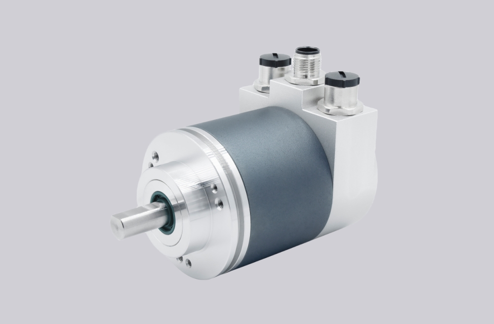
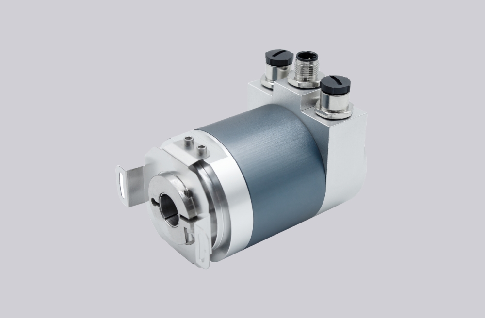
- 3 × 4-pin M12 radial connectors
- IP65 protection
- -20 °C to +70 °C temperature range
Typical production lead time: 15 working days.
The first weak point is not the absolute encoder core. It is usually PROFINET topology, device configuration, M12 shielding, IP/name assignment, or PLC cycle timing. If the network is wrong, the encoder can be mechanically normal and still deliver unusable position data.
Where the System Fails First
This model uses PROFINET IO, not SSI-only, Profibus, CANopen, analog, or incremental pulse output. The document specifies 100 Mbit/s Fast Ethernet, PROFINET V2.2, and RT/IRT support with cycle time ≥1000 µs. That means the system must be judged as an Ethernet motion-feedback node, not as a standalone sensor.
Typical failure points:
- Wrong device name or IP assignment → PLC cannot identify the encoder
- Poor M12 shield contact → intermittent PROFINET faults
- Port 1 / Port 2 topology error → link exists but data is unstable
- Wrong scaling or preset → position value is valid but wrong
- Shaft overload or coupling stress → mechanical feedback drift
- Weak 24 VDC supply → startup or communication instability
The pin assignment confirms two D-coded M12 PROFINET ports and one A-coded M12 power connector. X1 and X2 carry TxD/RxD pairs; X3 supplies 11–27 VDC and 0 V. This is where many field faults start: the network may show link, but poor shielding or wrong connector handling still creates unstable data exchange.
Mechanical and Network Boundary
Mechanically, this is not a high-load heavy-duty shaft unit. The document gives ≤6000 rpm mechanical speed, shaft load ≤40 N axial / ≤60 N radial, and typical bearing life based on lower operating load conditions. If the coupling is rigid or misaligned, the network will not show the root cause; the symptom may appear as unstable position behavior or repeated commissioning faults.
The encoder also supports programmable parameters such as addressing, resolution, CAM parameter, preset parameter, adjustment parameter, SSI parameter, and counting direction. These are not cosmetic settings. Wrong preset or counting direction creates a clean but incorrect position value, which is harder to diagnose than a total communication failure.
Installation Notes
- Keep the model format as CEV65M-10323
- Confirm PROFINET device name, IP assignment, and PLC hardware configuration
- Keep M12 shield contact continuous across both network ports
- Separate Ethernet routing from inverter and motor power cables
- Use Port 1 / Port 2 according to the real line topology
- Check green link LEDs and yellow data LEDs before replacing the encoder
- Keep shaft load within the documented axial/radial limits
- Verify preset, scaling, and counting direction before production startup
Key Data
- Model: CEV65M-10323
- Type: Absolute encoder
- Interface: PROFINET IO
- Resolution: 4096 steps / revolution
- Multiturn range: 4096 revolutions
- Supply voltage: 11–27 VDC
- Typical nominal current: 120 mA unloaded
- Transmission rate: 100 Mbit/s
- Cycle time: ≥1000 µs
- Flange: ZB36
- Shaft: 10FL / 19.5
- Connector: 3 × 4-pin M12 radial
- Protection: IP65
- Temperature range: -20 °C to +70 °C
- Mechanical speed: ≤6000 rpm
- Shaft load: ≤40 N axial / ≤60 N radial
- Vibration: ≤100 m/s², 50–2000 Hz
- Shock: ≤1000 m/s², 11 ms
- Parameter file: 24BIT_MULTI_149_EPN