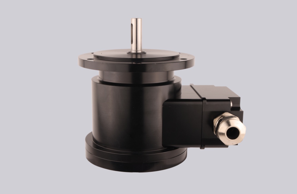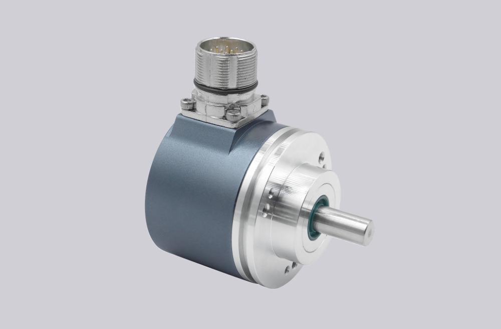



A custom compatible encoder solution can be provided for CEV100M-01169 in maintenance, retrofit, replacement, and upgrade applications. This configuration is typically used in systems requiring SSI absolute feedback, multiturn position continuity, and a face-flange encoder with 12 mm shaft arrangement and PG 90° cable outlet. Typical production lead time: 15 working days. During engineering review, key matching points usually include SSI signal continuity, 4096 × 4096 resolution structure, RS422 output level, ZB80 flange fit, shaft dimensions, and field wiring continuity under existing installation conditions.
Technical Overview of the CEV100M-01169 Encoder
The CEV100M-01169 is a multiturn absolute rotary encoder with 4,096 steps per revolution and 4,096 revolutions, using binary code and SSI output structure. The published electrical data shows 11–27 V supply voltage, RS422 output level, IP65 protection, and operating temperature from –20 °C to +70 °C. This combination makes it suitable for industrial feedback systems where stable SSI transmission and multiturn absolute position retention are required.
Mechanically, this version uses ZB80 flange construction, shaft type 12RD/24, and a PG 90° connector position with 10 m cable. The drawing on page 2 also shows the centered flange layout, 12 mm shaft geometry, and right-angle cable outlet, which are important when replacement work must preserve the original mounting envelope and cable exit direction.
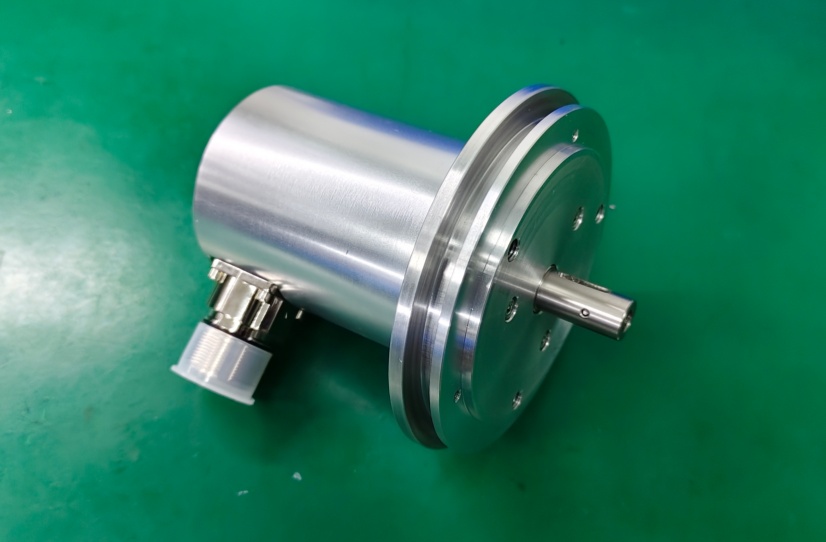
Custom Solution Photos
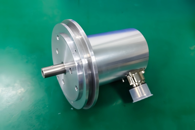
Industrial Integration Considerations
The first integration checkpoint is SSI feedback continuity. A compatible solution should preserve the original controller-side expectation for binary multiturn data, RS422 signal level, and direction input behavior. Even where the nominal resolution is correct, replacement work can still fail if signal handling, wiring assignment, or controller interpretation differs from the original field configuration.
The second checkpoint is mechanical installation continuity. The page 2 drawing indicates an 80 mm centering-related flange arrangement, 12 mm shaft format, and PG11 cable outlet. In retrofit projects, flange face, shaft engagement length, mounting hole pattern, and cable outlet direction should all be reviewed together rather than treated as separate details. This helps reduce bracket changes, cable rerouting, and service-side interference.
A further point is auxiliary signal continuity. The datasheet lists incremental tracks at 1024 PPR (5 V) together with A, /A, B, /B and direction input, so a compatible solution may also need to preserve this mixed feedback structure where the original system uses both absolute and incremental channels.
Field Installation and Wiring Notes
For this model, field installation should focus on the cable-outlet wiring format. The pin assignment page shows SSI Clock-, SSI Clock+, Data+, Data-, Channel A, /A, Channel B, /B, Direction input, supply, and ground on a 12-pin arrangement with cable outlet. During retrofit, conductor mapping should be checked point by point instead of assuming that similar cable colors or pin counts automatically mean the same function.
SSI signal pairs should be routed with attention to shielding continuity and separation from power switching lines. Direction input behavior should also be checked during startup so that counting direction remains aligned with the original control logic. Where the incremental channels are used for monitoring or secondary feedback, A/B channel continuity should be confirmed before commissioning.
Mechanical installation should focus on shaft fit, flange centering, and the 90° cable outlet direction. The page 2 drawing also notes a bending radius requirement related to the standard cable type, so cable exit space should be checked before final installation to avoid excessive stress near the gland and outlet area.
Custom Compatible Encoder Solution
A custom compatible encoder solution for CEV100M-01169 typically focuses on:
- SSI multiturn feedback continuity with 4096 × 4096 structure
- 12 mm shaft and ZB80 flange installation fit
- PG 90° cable outlet and 10 m cable arrangement continuity
- RS422 signal level and controller-side wiring compatibility
- Optional incremental track continuity where the original system uses A/B channels
These points should be confirmed during engineering review to ensure alignment with the original working configuration.
Lead Time and Custom Development
Typical production lead time: 15 working days.
Custom development usually starts with confirmation of SSI structure, flange and shaft dimensions, cable outlet direction, and field wiring requirements before final release.
Typical Technical Parameters
| Parameter | Specification |
|---|---|
| Model | CEV100M-01169 |
| Encoder Type | Multiturn absolute rotary encoder |
| Steps per Revolution | 4,096 |
| Number of Revolutions | 4,096 |
| Interface | SSI |
| Code | Binary |
| Supply Voltage | 11–27 V |
| Output Level | RS422 |
| Protection Class | IP65 |
| Operating Temperature | –20 °C to +70 °C |
| Flange Type | ZB80 |
| Shaft Type | 12RD/24 |
| Connector Position | PG 90° |
| Cable Length | 10 m |
| Pinout No. | ST2010A |
| Additional Signals | CH1 + CH2 + NEG |
| Direction Input | F/R |
| Incremental Tracks | 1024 PPR (5 V) |