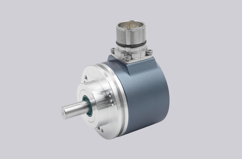
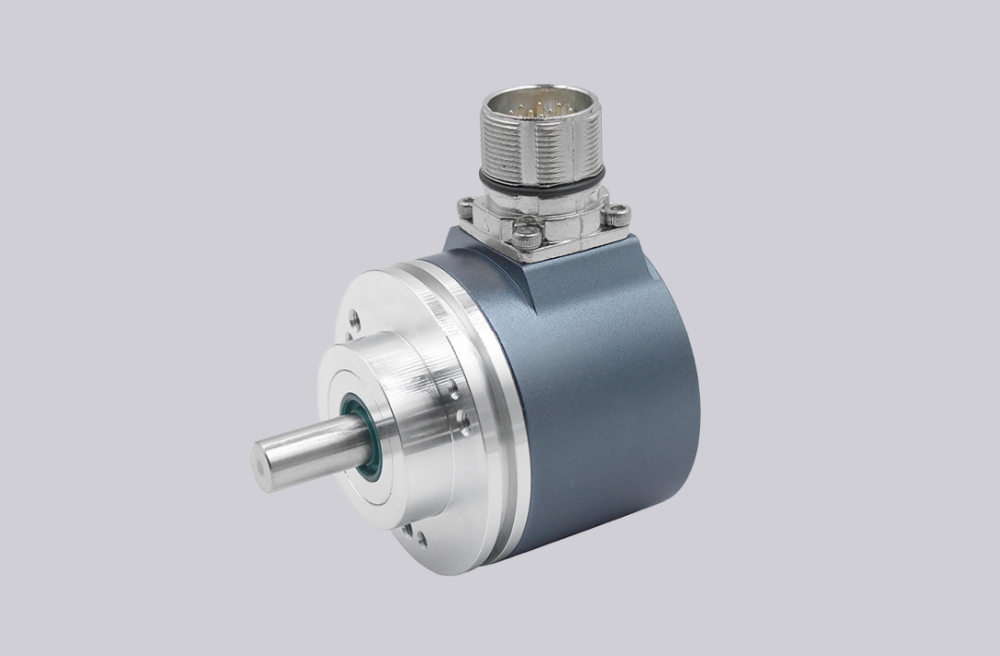
For AMG81S25Z0, EncoderWorks can provide a custom compatible replacement solution for SSI absolute multiturn feedback systems where the key checks are 25-bit SSI word length, 13-bit singleturn scaling, 12-bit multiturn rollover, and IP55 installation limits. This version should not be treated like AMG81S13Z0, because the controller may depend on absolute travel position across multiple shaft revolutions, not only one-turn angular feedback. Typical production lead time: 15 working days.
This model belongs to the AMG 81 absolute encoder series with EURO flange B10 and ø11 mm solid shaft. In the AMG81S25Z0 configuration, “S” defines the SSI interface, “25” defines 13-bit singleturn plus 12-bit multiturn position, and “Z0” means without additional incremental output. Replacement work should focus on SSI clock/data timing, controller-side word length, Gray-code interpretation, multiturn count behavior, shielded wiring, shaft load, and enclosure suitability.
System Limits
The main system limit is SSI timing and word length. The controller must read the encoder with the correct clock frequency, 25-bit data structure, and wait period. If the SSI input is configured for a 13-bit singleturn word or a different sampling window, the position value may shift, freeze, or appear stable but offset from the real axis position.
The second limit is multiturn scaling. AMG81S25Z0 combines 8192 steps per revolution with 4096 revolutions. A replacement should be tested through one full shaft revolution and across several turns, because singleturn movement can look correct while the multiturn count is still wrong.
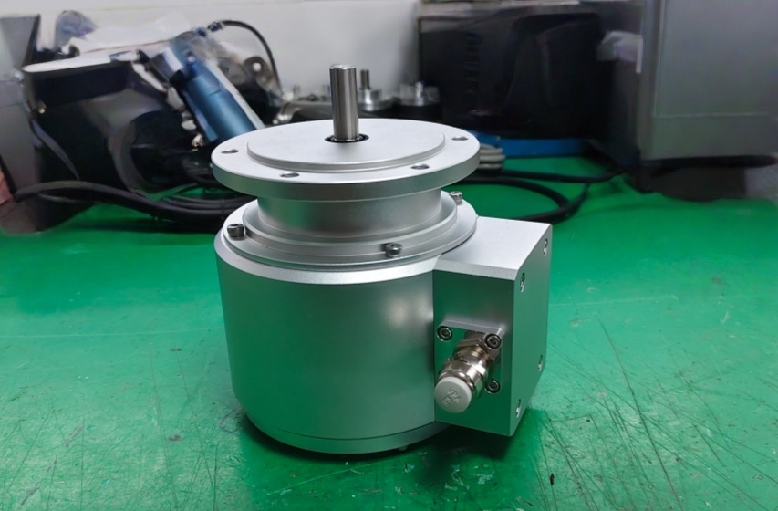
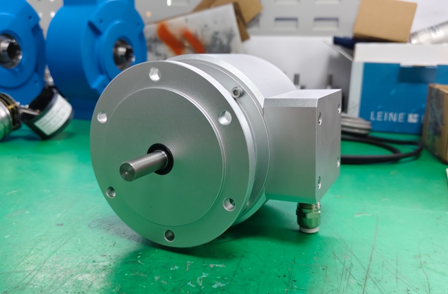
The installation limit is the ø11 mm solid shaft, EURO flange B10, and IP55 protection class. Coupling misalignment, axial preload, radial force, poor shielding, or exposure beyond the enclosure rating can reduce reliability, especially near inverter, motor, brake, or contactor wiring.
Wiring & Installation
Before removing the existing encoder, record the SSI clock and data wiring, controller word length, clock frequency, wait time, Gray-code setting, supply voltage, shield connection, and mechanical zero position. The replacement should be checked against the controller’s SSI input configuration before startup.
After installation, confirm stable SSI communication and correct position reading from the controller display. Then test direction, zero alignment, one full shaft revolution, and multiturn counting across several turns.
Custom Compatible Solution
EncoderWorks can configure the replacement around the installed SSI multiturn system:
- Match SSI clock/data behavior, 25-bit word length, wait time, and controller-side sampling
- Verify 13-bit singleturn, 12-bit multiturn, Gray-code reading, direction, and zero alignment
- Adapt the EURO flange B10, ø11 mm solid shaft, M23 or bus-cover connection, and mounting requirement
- Review shield grounding, cable routing, SSI receiver margin, IP55 exposure, and shaft coupling load
Key Data
| Item | Data |
|---|---|
| Model | AMG81S25Z0 |
| Encoder type | Absolute multiturn encoder |
| Interface | SSI |
| Resolution | 13 bit singleturn + 12 bit multiturn |
| Steps per revolution | 8192 |
| Number of revolutions | 4096 |
| Code | Gray for SSI version |
| Additional output | Without incremental output |
| Supply voltage | 9–30 VDC |
| Flange | EURO flange B10 |
| Shaft | ø11 mm solid shaft |
| Protection class | IP55 |
| Shaft load | ≤50 N axial, ≤60 N radial |
| SSI clock frequency | 100–800 kHz |
| SSI wait time | 12–30 µs |
| Approval | CE / UL |