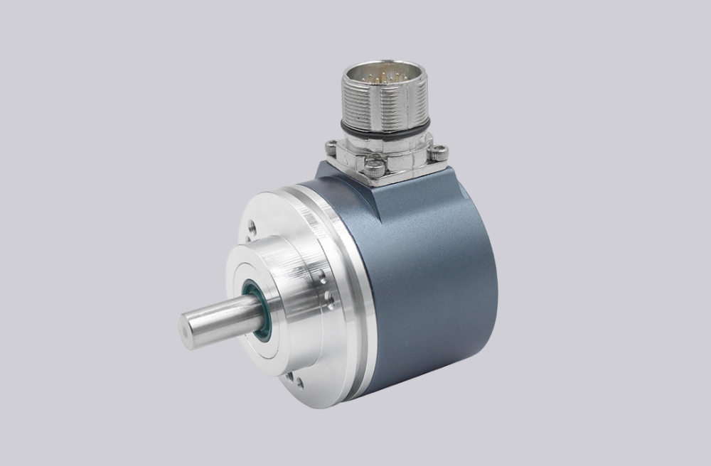
For 8.A12A.F86E.6112, EncoderWorks can provide a custom compatible replacement solution for large-shaft Modbus absolute encoder systems where the key checks are ø38 mm H7 bore fit, encoder-side locking-ring clamping, 70 mm torque-arm preload, Modbus RTU parameter matching, and radial M12 wiring. This model should not be treated like a Profibus AX encoder, because the fieldbus protocol changes to Modbus RTU and the adapter bore increases to ø38 mm. Typical production lead time: 15 working days.
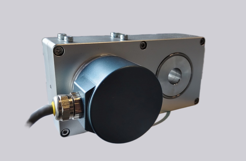
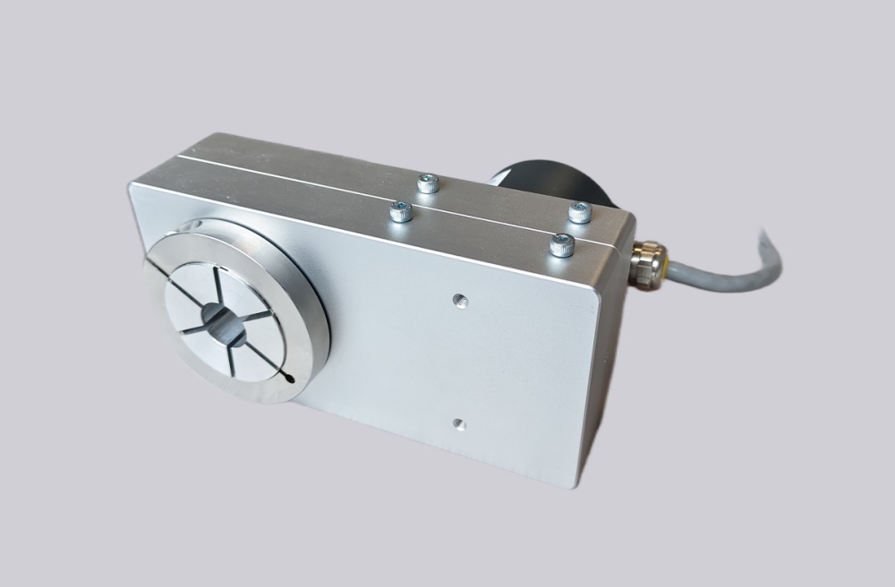
This configuration combines a Kübler AX hollow-shaft adapter with a Sendix F5868 absolute multiturn encoder. The AX section provides the ø38 mm hollow-shaft bore, locking ring on the encoder side, and 70 mm torque arm, while the encoder body provides Modbus RTU absolute position feedback through one radial M12 connector. Replacement work should focus on shaft fit, clamp torque, torque-arm alignment, Modbus address, baud rate, register mapping, scaling, preset behavior, and shield grounding.
System Limits
The first system limit is AX mechanical installation. The ø38 mm shaft must match the H7 adapter bore without forcing the clamp, and the locking ring must remain on the encoder side. Because ø38 mm belongs to the larger bore range, clamp torque, shaft runout, and torque-arm preload must be controlled carefully to avoid housing movement, bearing load, or repeatability drift.
The second limit is Modbus communication. The controller must preserve the original Modbus RTU address, baud rate, parity, register map, scaling, preset value, and counting direction. If the encoder powers up but the register interpretation is different, the PLC may read stable data while converting it into the wrong machine position.
The third limit is the AX operating envelope. The adapter is rated IP64 and has temperature-dependent speed limits. High shaft speed, high ambient temperature, or a loaded torque arm can become the practical failure boundary before the Modbus interface itself becomes unstable.
Wiring & Installation
Before replacement, record the Modbus node address, baud rate, parity, stop-bit setting, register map, preset value, scaling parameters, and direction setting from the controller project. Also record the radial M12 connector assignment for supply, ground, communication lines, and shield connection.
During installation, confirm the ø38 mm H7 shaft fit, keep the locking ring on the encoder side, and align the 70 mm torque arm without preload. Route Modbus and power cables away from inverter output wiring, maintain shield continuity through the M12 connector, and avoid ground loops between the encoder housing, machine frame, and cabinet earth. After startup, verify communication status, actual position register, direction, preset response, torque-arm movement, and repeatability over several machine cycles.
Custom Compatible Solution
EncoderWorks can configure the replacement around the installed shaft and Modbus system:
- Match the AX ø38 mm hollow-shaft adapter, encoder-side locking ring, 70 mm torque arm, and mounting envelope
- Preserve Sendix F5868 Modbus RTU position feedback, node parameters, register mapping, scaling, preset, and direction behavior
- Adapt the radial M12 connector layout, 10–30 VDC supply range, communication wiring, and shield grounding
- Review clamp torque, shaft fit, torque-arm preload, IP64 installation limits, and temperature-speed operating margin
Key Data
| Item | Data |
|---|---|
| Model | 8.A12A.F86E.6112 |
| Encoder type | Absolute multiturn encoder with AX hollow-shaft adapter |
| Encoder body | Sendix F5868 |
| Interface | Modbus RTU |
| Protocol | Modbus RTU Application Protocol V1.1b3 |
| Supply voltage | 10–30 VDC |
| Bore | ø38 mm H7 hollow-shaft adapter |
| Locking ring position | Encoder side |
| Torque arm | 70 mm |
| Connection | 1× radial M12 connector |
| Adapter protection | IP64 |
| Adapter weight | Approx. 3.5 kg |
| Starting torque | Max. 0.15 Nm at 23°C |