We developed a custom solution for model OCD-PPA1G-0810-C060-PRT. Selected when multi-turn absolute feedback is required through a parallel push-pull interface, using a 58 mm clamping flange and 6 mm solid shaft, without changing an existing parallel-control architecture. Typical production lead time: 15 working days. The referenced configuration is an optical version with 10-bit single-turn resolution, 8-bit multi-turn resolution, Gray code, a mechanical gear train without battery, 10–30 VDC supply, and a radial 26-pin M23 connector.
Key Specifications
- Interface: parallel push-pull
- Resolution: 10-bit single-turn + 8-bit multi-turn
- Code: Gray
- Multi-turn: mechanical gear train, no battery
- Supply: 10–30 VDC
- Protection: IP65 shaft side, IP65 housing
- Structure: 58 mm clamping flange, 6 mm solid shaft, 10 mm shaft length
- Connection: radial M23 male, 26-pin
- Speed: up to 12000 rpm
Decision Snapshot
- Best for: parallel absolute retrofit systems needing multi-turn retention with connector-based wiring
- Key fit: 6 mm solid shaft
- Avoid if: the system is based on fieldbus communication or only requires incremental feedback; the published interface, connector layout, and 18-bit direct output map point to a classic parallel architecture rather than a bus-based one.
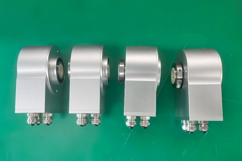
Custom Solution Photos


Encoder structure reference: 58 mm clamping flange, 6 mm solid shaft, radial M23 connector.
Signal & Output Architecture
This model uses direct parallel output rather than protocol-based data transmission. The connection plan provides Bit 1 through Bit 18 plus Latch, DIR, Power Supply, and GND, which is the expected structure for direct controller-side reading of multi-turn absolute position.
Primary integration value: direct hardware-level position reading without bus setup.
Primary limitation: this structure increases sensitivity to controller-side mapping, cable discipline, and connector integrity compared with Profibus or Ethernet-based encoders. That is an engineering conclusion based on the 18-line output structure and push-pull interface.
Mechanical & Installation Focus
The shaft is only 6 mm, while the published maximum mechanical speed reaches 12000 rpm and the listed shaft load is 40 N axial / 110 N radial. At this combination of small shaft and high speed, coupling alignment matters more than the nominal flange size. Poor alignment will show up first as vibration, bearing stress, and unstable signal behavior under dynamic load.
Wiring & Installation
The radial M23 connector simplifies field replacement compared with loose cable wiring, but the primary commissioning risk remains incorrect controller-side bit mapping. Check order should be: pin assignment → Latch logic → DIR logic → power reference. That sequence is an engineering recommendation based on the published pinout and direct bit architecture.
Integration & Compatibility
- Designed for parallel absolute encoder systems
- Matches 58 mm clamping flange installations with 6 mm solid shaft
- Suitable for multi-turn position feedback without battery replacement
- Not suitable for bus-based control structures or simple incremental feedback use cases.
Lead Time
Typical production lead time: 15 working days. Custom adaptation can be developed around shaft fit, connector layout, signal assignment, and installation requirements.
Key Technical Data
| Item | Data |
|---|---|
| Model | OCD-PPA1G-0810-C060-PRT |
| Interface | Parallel push-pull |
| Type | Absolute multi-turn |
| Sensing | Optical |
| Resolution | 10 bit + 8 bit |
| Code | Gray |
| Multi-turn | Mechanical gear train |
| Supply | 10–30 VDC |
| Protection | IP65 |
| Flange | 58 mm clamping flange |
| Shaft | 6 mm solid |
| Shaft length | 10 mm |
| Connection | Radial M23, 26-pin |
| Speed | 12000 rpm |